It all looked so easy when you did it on paper
Milton W. Rosen, Rocket engineer, 1956
where valves never froze, gyros never drifted,
and rocket motors did not blow up in your face.
On the 14’th of this month, I got a message that there was a launch opportunity today, the 28’th.
Meaning I had exactly 2 weeks to get a rocket together.
And we did.
The launch however did not go according to plan.
But first, how we got here:
Overview
Like last time, an index is provided since rockets are complex, and as such this post is long
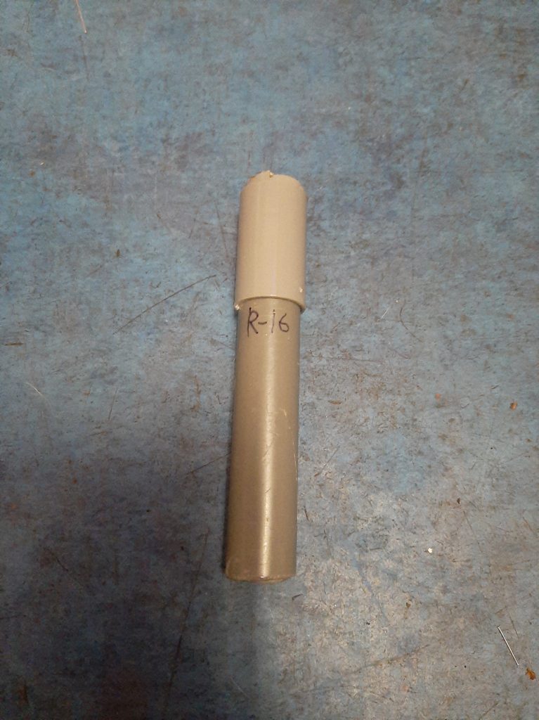
R-16
RA-1
Other Changes
The Launch Setup
The Launch
After the spectacular launch of Perigee, It was quickly decided to, and I quote, “Just launch another one”.
Meaning, a rocket of the BTIR-2 design, just retrofitted with features such as a parachute system.
However, due to the incredibly strict deadline, it was decided to Keep it simple, stupid.
Therefore, large, multi discipline changes were to be postponed to a future launch, with this one focusing on a few simple adjustments:
- Angled Fins to add a rotation, in an attempt to improve stability
- The RA-1 Rocket Altimeter, to log data
- The adaptation of the standard NERO color scheme
- And minor improvements to the design with what was learned from Perigee
- Mainly improvement of the screw thread tolerances, and the strengthening of the bulkhead the motor pushes on, as it was breached last time
I clearly failed in my quest to keep it simple, as I have significantly altered the aerodynamics and mass (placement) of the rocket this way.
For reasons unclear, it seemed reasonable at the time.
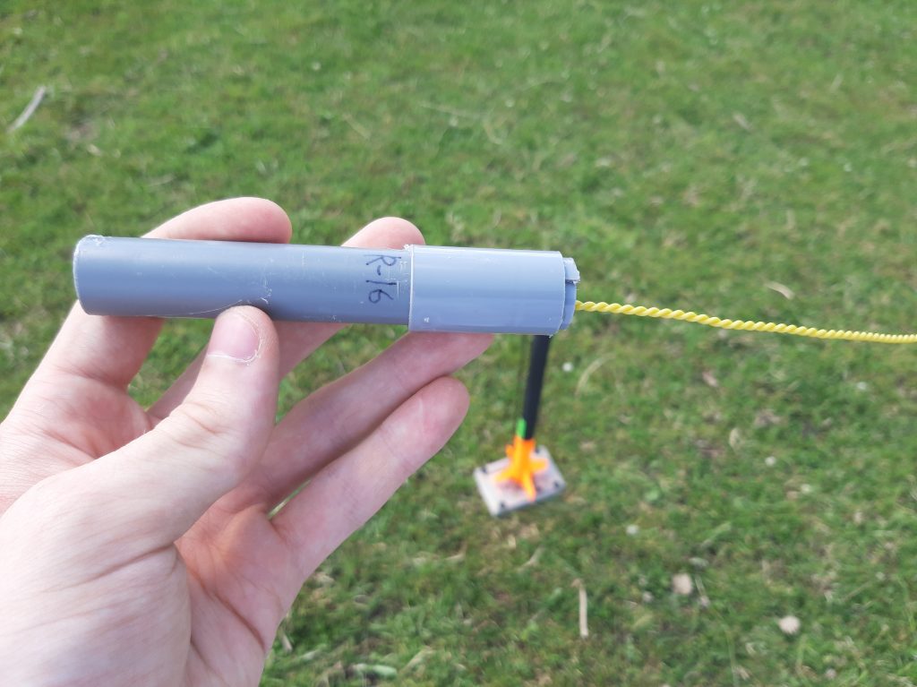
R-16
While there is work going on to develop an aluminium cased, reusable rocket motor, the time limitations at work made us decide to use proven technology we could fabricate over the weekend.
As such, the PM-19 design was chosen.
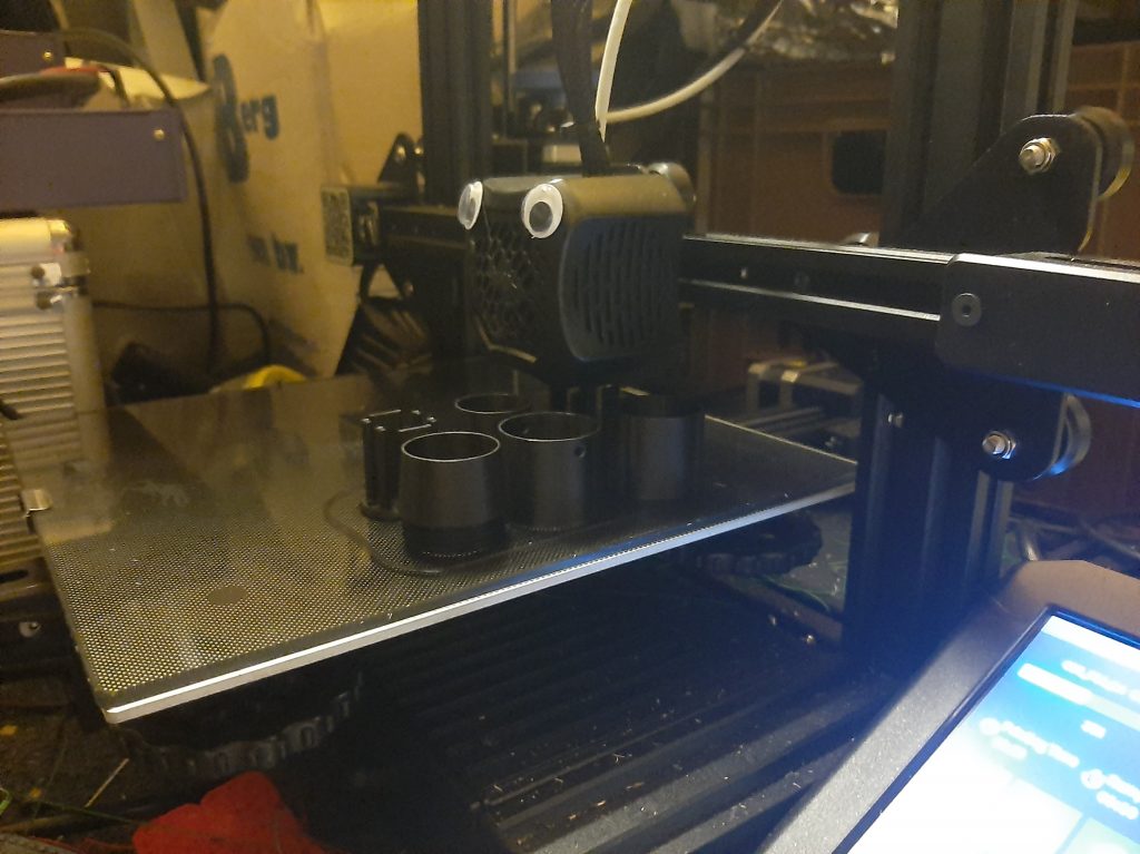
There are no pictures of the fuel casting process itself, but this has been done and documented many times now, so I refer the reader to any of the 15 other R-n rockets documented on this site.
I do however have sign out pictures of the cast grain, and nozzle assembly:
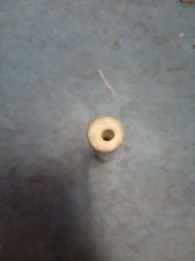
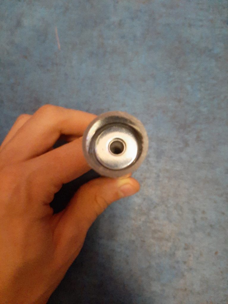
Not much to say here, really.
RA-1
I’ve had a long history with flight computers, assuming you think a year is long.
Including RA-1, I’ve made 3.
which is in start contrast to most people, who make an average of zero rocket flight computers over their lifetime.
So while I’m not saying I’m any good at it, I will say I have experience.
And something I’ve learned is that I keep dreaming too big.
All kinds of sensors, the best of the micro controllers, advanced functionality and large budgets.
Considering this, its not a big surprise I did not have any flight ready avionics laying around for this launch, so I had to make some.
And that’s where KISS (no, not that one) comes in.
I already knew this launch would not use a parachute, so all I needed the avionics to do is measure and store altitude.
Whats the easiest way to measure altitude electronically? A barometer.
For those out of the loop, a barometer is a device which can measure air pressure.
And since the atmosphere gets less dense the higher up you go, you can correlate the pressure decreasing to an increase in height with some math and lookup tables.
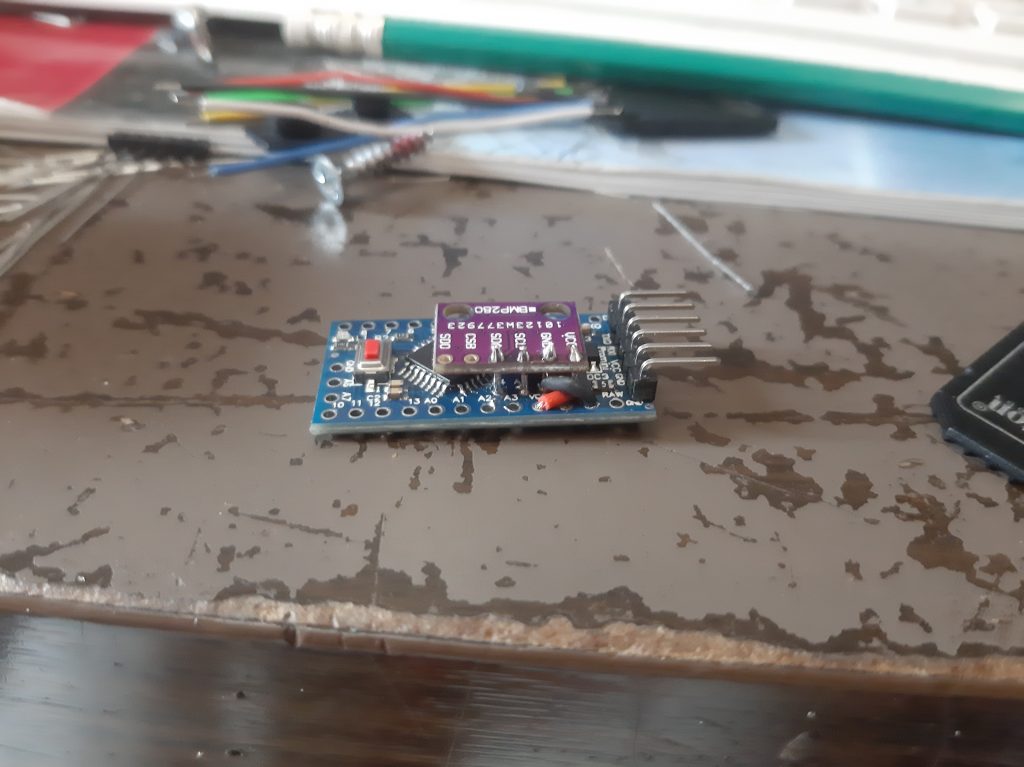
Thus, a Bosch BMP-280 was swiftly purchased.
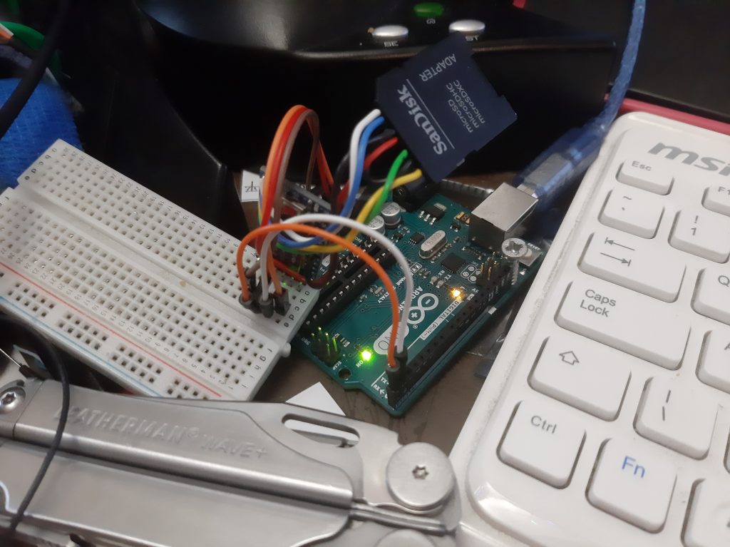
To log data, you first need a way to take measurements from the instrumentation (aka the barometer), but also something to store it on.
For storage I prefer MicroSD cards due to their insignificant size and weight, high capacity / speed, availability, standardization, and how trivial it is to access the data on it.
Having an Arduino talk to a MicroSD is a matter of wiring it up and installing a standard library.
Having it talk to some 4MB flash memory on a breakout board is simply slightly harder, and I wanted to keep everything simple.
And again, I chose the simplest and cheapest way to do both:
I took a MicroSD to SD card adapter thingy I had laying around, and soldered straight to the “Pads”, like such:
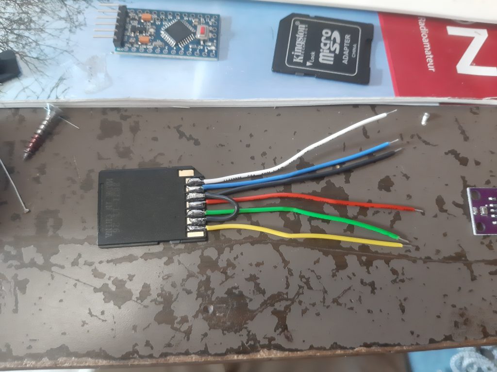
And I chose an Arduino which had 3.3V logic (In this case, a clone of the Pro Mini), so no level conversion magic had to happen to interface it (why logic levels matter and what an SPI interface even is is out of the scope of this paragraph, and is left as an exercise to the reader)
Then, I simply soldered the BMP-280 Barometer to the I²C pins of the Pro Mini
(If I lost you there, I simply said “I connected the sensor to the tiny computer”)
And then I soldered the pins of the SD card construction to the Pro Mini:
Using an improvised “programming jig”, fashioned from a breadboard and a Arduino Uno with its chip lifted, I was able to upload the code.
The code itself was also no more complex than needed:
Upon power up it assumes its got a working MicroSD card and Barometer, and after initializing for a few seconds, it takes 3 measurements (pressure, temperature, and altitude), combines them into a single String (collection of text for the non programmers), writes the string to a text file on the MicroSD card, and then repeats.
It does this (or attempts to do this, at least) every 20 Milliseconds.
That’s 50 times a second!
I don’t actually know if it manages to do this, seeing as taking measurements takes time, but I think it gets pretty close.
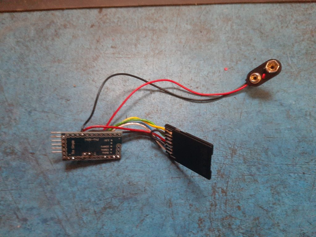
I then glued the 2 parts together, and strapped it to a battery for testing:
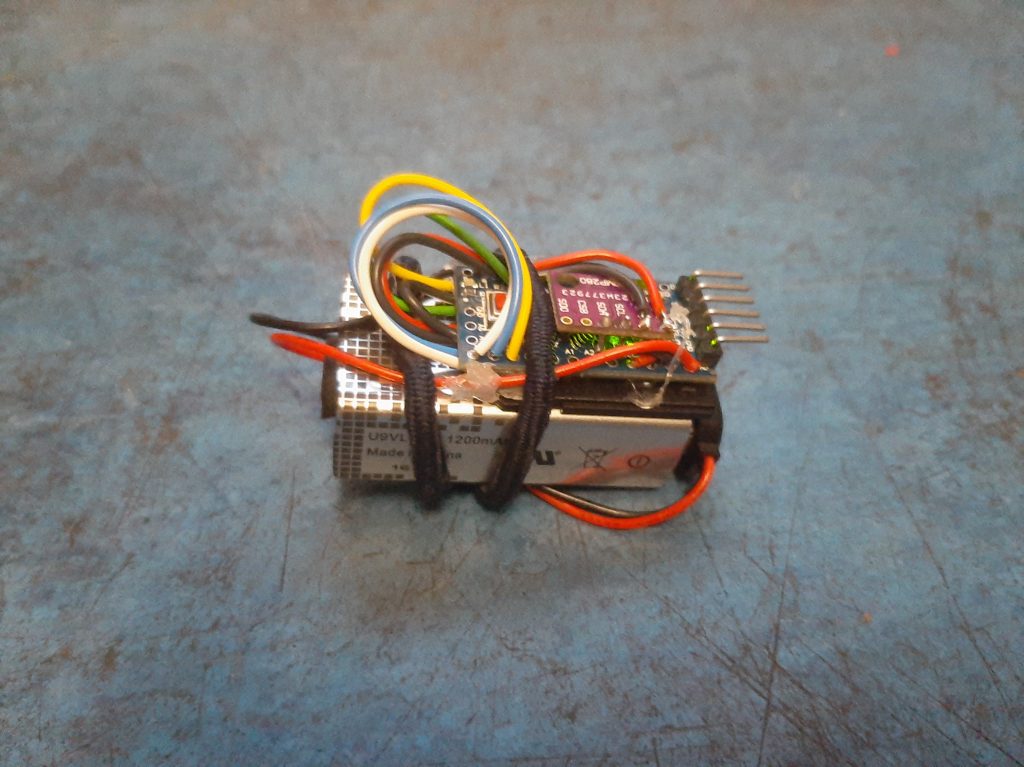
As you can see, I’m using a PP3 “9 Volt” battery.
This has 2 main disadvantages:
- Its rather large (Compared to a lithium-ion polymer battery of sufficient capacity)
- Its rather heavy (again, in comparison with LiPo technology)
I thought “I have an entire fuselage segment to put this in, and this way its mass is closes to the large flight computer I’m developing”
Basically: Its not a bug, its a feature.
This was however before I had the chance to print the fuselage segments, so I soon discovered the flaw in my plan:
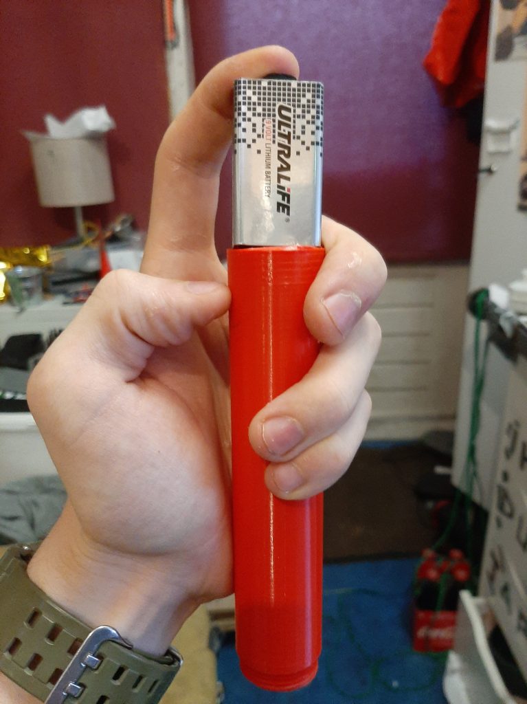
While the fuselage itself is large enough to hold the battery, I forgot to account for the screw threads…
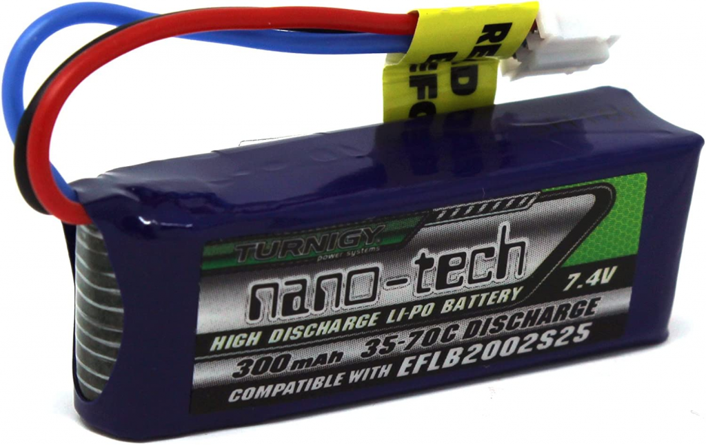
Thus, the battery of ongoing RFC-2 project was commandeered, and hastily retrofitted to power it instead.
This battery is a better fit, being a very small 2s NanoDrone LiPo Battery:
For reference, the assembly and code was all done over the course of an evening, with the battery retrofit and integration being the subject of another short afternoon.
I kept it simple.
Then, it was time to integrate this construction into the avionics bay.
This was achieved by making 2 “skeletons”, which consist of a small round base which allows them to fit into the BTIR-2 fuselage without experiencing lateral excursions.
4 to 6 posts are integrated on top, to stop the part from wiggling, and 2 3mm holes are left in the bottom so that a tie wrap can fit trough and around to keep it in place.
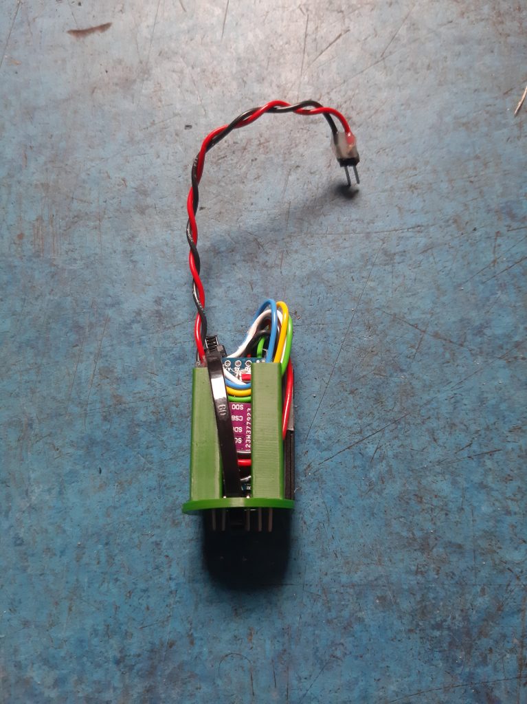
(Note the programming header sticking out the bottom)
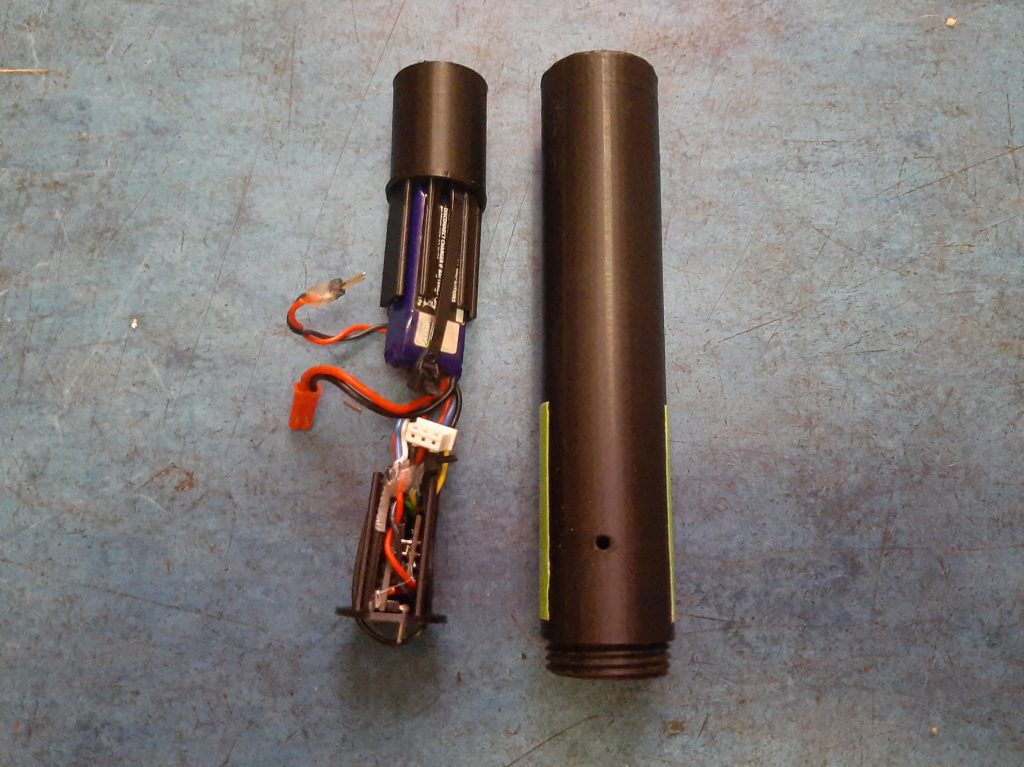
The avionics bay is simply a standard fuselage segment, with 4 3mm holes being left by the 3D printer.
This is to attempt to allow pressure equalization, or it would only be measuring the pressure of where it was inserted.
A spacer was added to the top so that the screw thread of the fuselage segment on top would push RA-1 and the battery sufficiently close to negate rattling, but not so close that they would break.
Simplicity itself, even though I can’t explain it simply.
The important part is that it functions, measuring pressure, temperature, and most importantly: altitude
It does this 50 times a second, and stores it on a MicroSD card.
If somebody wants more detailed information, such as schematics and the code, please contact me.
Now, onto:
Other Changes
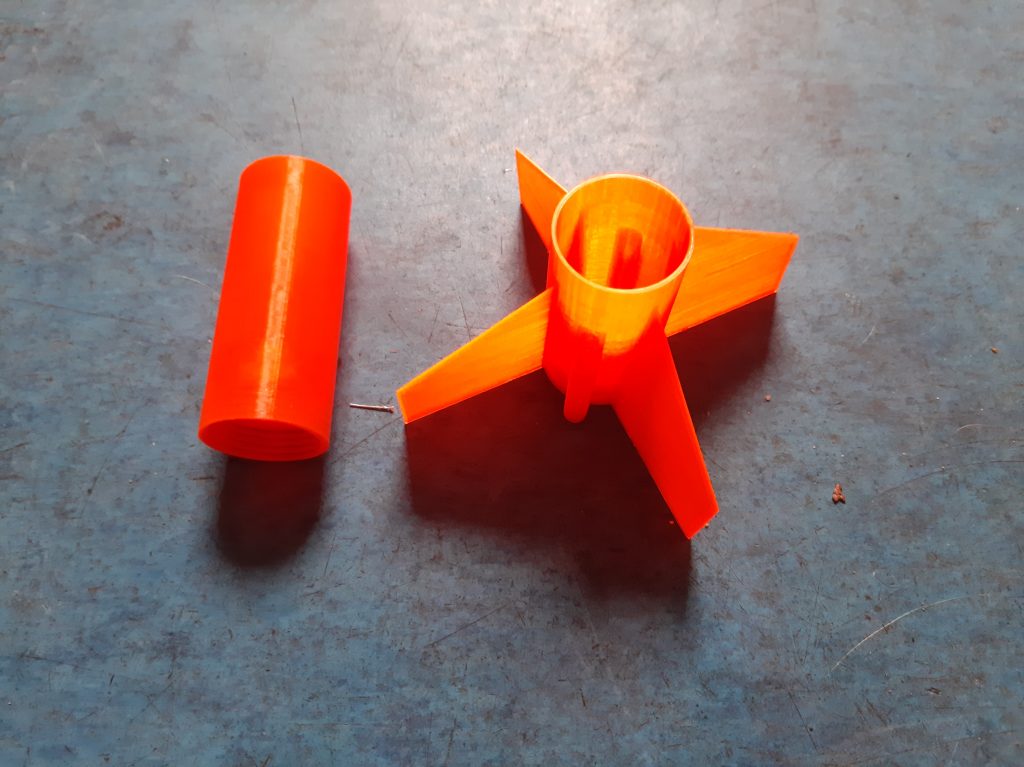
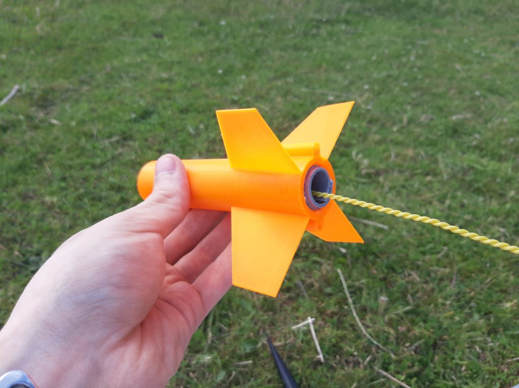
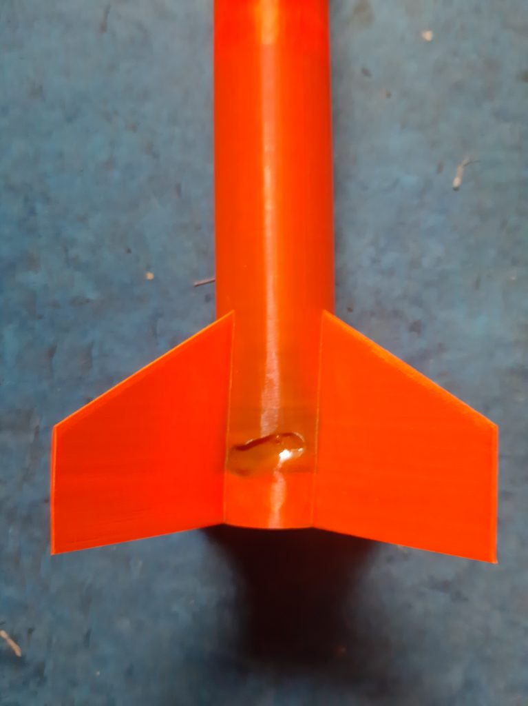
As mentioned in the Overview, I changed up the fins and the colors.
Starting with the fins, I simply rotated them 5 degrees, which felt about right.
Remember, this is an experiment for experimentation’s sake, so if this didn’t work out all was well.
And I still don’t trust the simulations too much, so I wanted to see what the effect would be.
The main problem here was changing multiple variables, but that’s a problem for the Launch section to explain.
Then, the colors.
Ive been told, that the NERO, the oldest Dutch experimental rocketry club, has historically used black rockets with orange fins.
The reason I was given, which sounds very reasonable, is that black contrasts the best against both blue and white (as in, the sky), and that having an orange tail allows easier recovery when it “goes ballistic”, and ends up sticking nose first in the dirt.
The orange is easy to see, and contrasts better than black against the often more brown colors of nature, and can still easily be seen amongst grass.
And by having it at the tail, it also sticks up above the grass if it “Lands” nose first.
And lastly, orange is not a color that occurs in nature in the Netherlands, so it won’t be confused with a flower at a large distance, as red might be.
This all seemed well thought out, and since I have recently become a member of NERO, it only felt reasonable to adapt their perfected, functional color scheme.
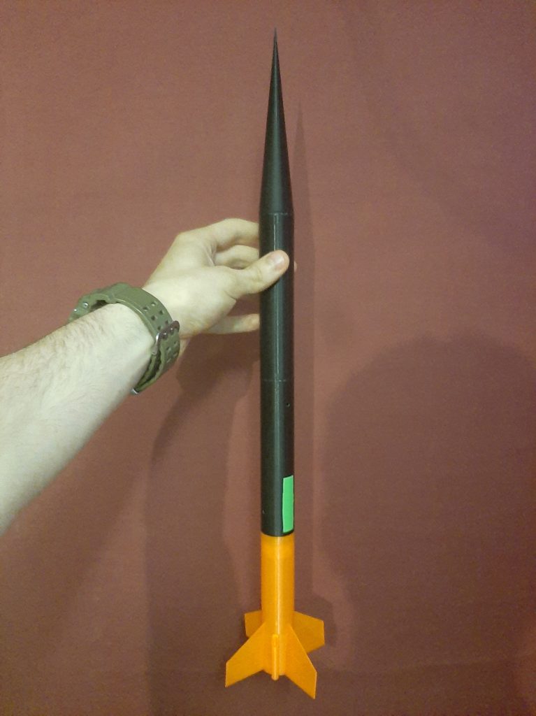
And, since the entire rocket has been 3D printed in the form of 4 modules, I only needed to buy correctly colored plastic, and print the appropriate parts with it.
So I did:
Pardon the Dutch Angle
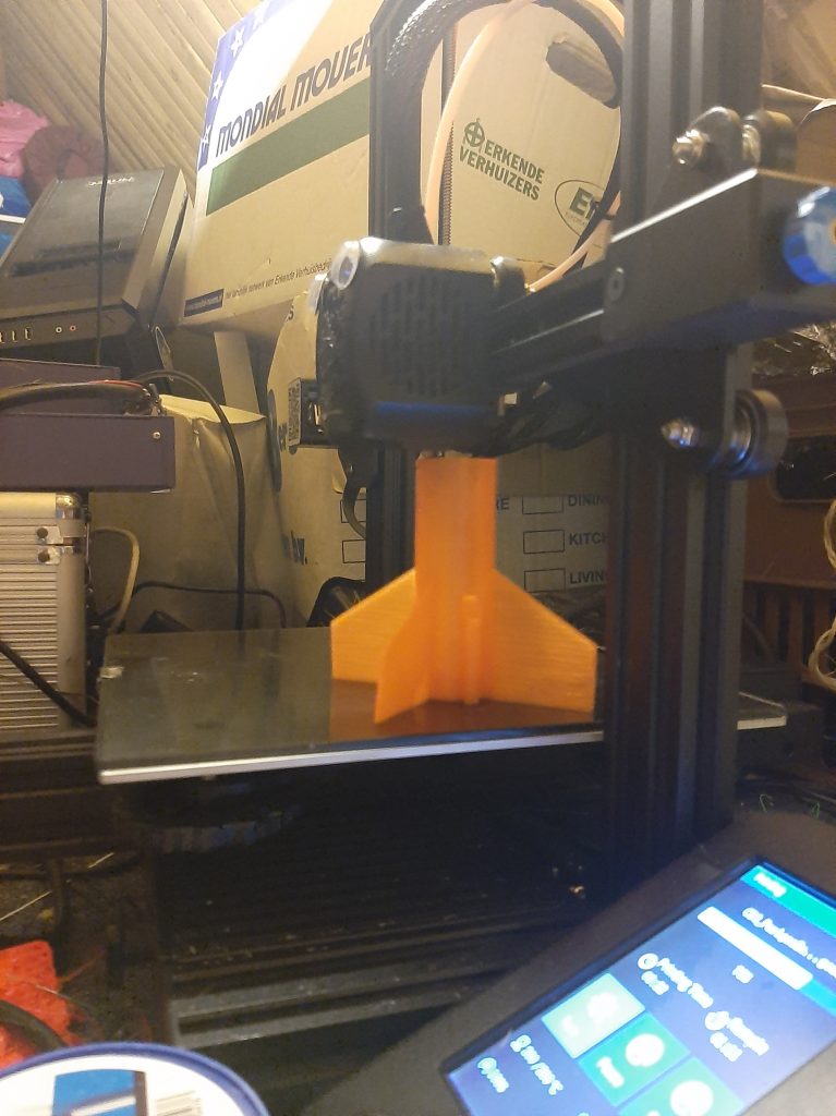
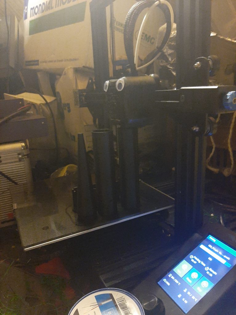
Some prototyping and repeated printing later, and the rocket was complete!
This was intended to show the rotation more clearly
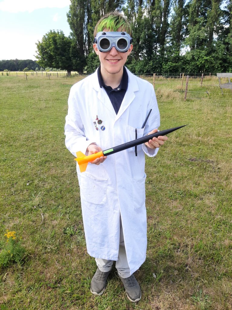
With everything ready, it was time to go to the launch site.
The Launch Setup
It was a beautiful day, with the sun shining, and barely any wind.
Like last time, the equipment was unpacked and deployed, systems were being tested, and Perigee-2 was being assembled.
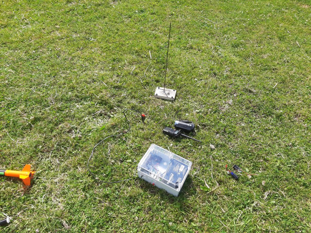
Like last time, it also had an “Administrative Document” as a payload, with my personal contact information, and a short synopsis of the planned launch.
There are however very little pictures of the preparations, since we were mainly getting on with it.
I also wish to note the difference in mood with last time:
It was described as “Just another day in the office”, last time was the first time that we had done anything on this scale, this time it was basically just the same again.
It didn’t feel “Special”.
I get how stupid that might sound, we were launching a rocket!
Hence why I found it worthy of note.
The Launch
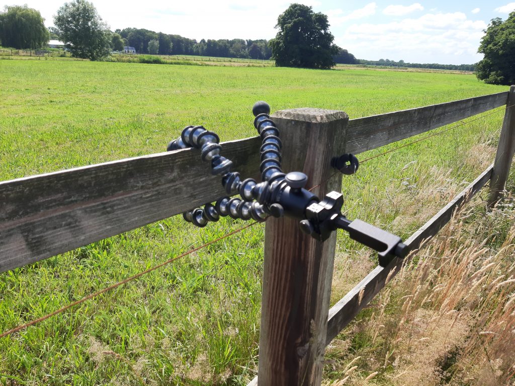
Like above, there is a lot less footage than last time, although this was not necessarily out of laziness.
There were some… Anomalies.
Of the 6 cameras we tried to setup (2 phones, 1 handheld, 1 wideshot, 1 slomo), 2 were defective before deployment, with one failing shortly before the launch!
The GoPro knockoff which was supposed to do the slomo, and was supposedly charged, turned out to be dead.
Some UI designed had decided to make the empty battery symbol look like a more grey full battery symbol.
We had a backup camera, but the cards were not interchangeable.
The wideshot was also a problem, due to a lack of MicroSD cards to fit in the cameras.
I had prepared for this by 3D printing an extra phone holder, so a small tripod could hold the phone of one of the spectators.
It broke when they tried to insert their phone.
Since they are lovely, I will blame my 3D printer and not user error, but it was broken either way.
This was worked around by precariously balancing it in the bottom part of the clamping mechanism.
And the phone that was supposed to do the closeup stopped recording after 3 minutes.
It is unclear whether it was a lack of storage, it overheating in the direct sunlight, a bit flip from space radiation, a fly pressing the stop button, or just plain bad luck.
Either way, we only managed to record with 2 phones and a handheld Sony HandiCam.
This is also why we brought 5 cameras in the first place, redundancy.
With that out of the way, lets continue onto the countdown!
As you might be able to guess, it was not supposed to do 2 back-flips and crash.
And as I hope is understandable, with simulations telling me it should reach 80 meters quite stabily, I was slightly disappointed at this unexpected result.
Still, Data was gathered, although learning from it is hard since I have no idea what actually happened.
I have some hypotheses, such as:
- Instability from the rotated fins
- Instability from the shifted center of mass due to the avionics
- Instability due to weird vortex sh*t from the tape
- Instability due to a motor defect deflecting the thrust
- A mix of the above
- None of the above
All I can say for sure, is that it took a right turn, and it wasn’t supposed to.
I did design it to rotate, but not on that axis!
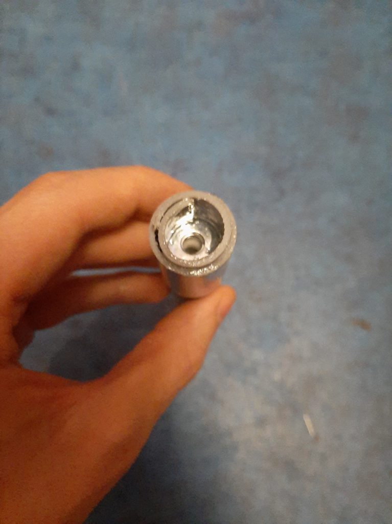
Something else of note is that upon recovery, the side wall of the core stage, near the nozzle, was molten.
And not like it was slightly deformed, it was a liquid!
Seeing as PLA melts at around 170/180 Celcius, there had obviously been a motor defect.
Another sign was the visible charring around the molten plastic, indicating that exhaust, fire, or both had gone where they shouldn’t.
The orange less.
I would need to perform an autopsy to make sure, but it seems to me like the nozzle retaining tube burned trough, either during flight, or directly after.
The melting suggests it was not latent heat, but flames, so I think its more likely it was during burning.
This would suggest my theory that:
- The motor didn’t burn as fast as it should have
- Either due to “soggy fuel”, nonoptimal grain structure, incomplete ignition, or a nozzle failure.
- And that possibly, thrust shifted (or more aptly, vectored) to the side during burning
- This would explain the excursion to the right, and also the burn trough, as exhaust could slip past the side of the now shifted nozzle ring
- Another clue could be that the grain was especially asymmetrical this time around, although this has rarely been a problem for us
Either way, another anomaly.
Suprisingly, RA-1 functioned according to its specifications, and it diligently took and stored 73935 measurements!
Of these, I took 238 altitude measurements to compile this graph:
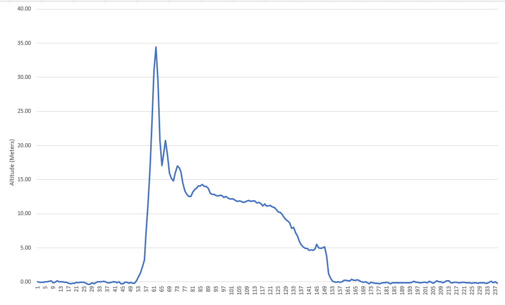
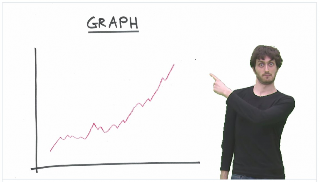
As you may have noticed, there is a rather a large spike in that data.
And since I can safely say the rocket did not reach 35 meters, you could say the data is wrong.
I however, believe the data to be correct, even though the results are not.
Allow me to explain:
The barometer measures pressure, as previously discussed, and when the rocket shoots up I think the acceleration temporarily evacuates an excess of air from the avionics bay, creating a partial vacuum and elevating the measured altitude.
To compensate, the BMP-280 has a algorithmic filter built in.
However, I turned it off.
My reasoning behind this was that if I could get the raw data, I could filter it any way I wished in post using mathematics, instead of being stuck with whatever the BMP-280 thought was appropriate.
And since it would have filtered by taking multiple measurements and then averaging them, simply taking multiple measurements should allow me to do just that.
I anticipate that once filtered, the graph should approach the 20 meter mark in a smooth way, like the trajectory would imply.
I say anticipate because I will first need to write a filtering algorithm and crunch the numbers.
Another thing is that I ensured is that it also saved the raw temperature and pressure readings.
From this, one can deduce altitude, so I can use that to verify its own internal calculations.
Data Data Data.
And, as always, the raw data is supplied inside a .7z file
I also recommend Notepad++ for viewing and editing
Another thing of note is the state of the launch pad after launch
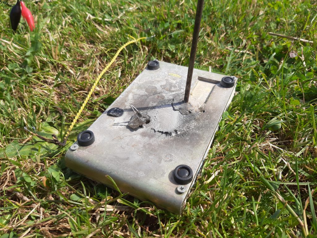
There had been enough force to blast a small support structure off its hot glue foundation
Turns out a rocket exhaust contains a lot of energy!
And because I failed to find an organic place to introduce this, the mass of the rocket and some of its various parts:
| Perigee 2 (Complete with RA-1 and PM-19) | 158.56 grams |
| R-16 (Wet mass) | 51.18 grams |
| RA-1 (With skeletons and spacers) | 34.96 grams |
| Perigee 2 (Dry mass, extrapolated) | 72.42 grams |
| Perigee 2 (Complete, after recovery) | 138.69 grams |
| Spent fuel (Extrapolated) | 31.31 grams |
Thank you for reading, and stay tuned for further exiting experiments followed by boring, detailed reports.
Too bad about the burn through! With rockets, failure is always an option. I can really recommend measuring where the c.g. of your final rocket it by balancing it using a string, that helps exclude some weird stability issues. Also too bad you didn’t get to see if the fin cant had any effect.
The new electronics bay looks really fancy btw!