
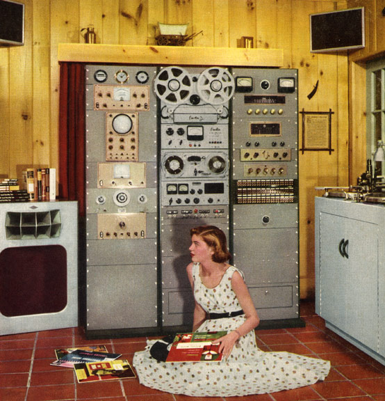
If we could have devised an arrangement for providing everyone with music in their homes, perfect in quality, unlimited in quantity, suited to every mood, and beginning and ceasing at will, we should have considered the limit of human felicity already attained and ceased to strive for further improvements.
— Edward Bellamy, Looking Backward, 1887
I listen to a lot of music.
Whenever I am not either talking to someone or attempting to sleep, there is usually something playing in the background.
So, given I listen to music in such prodigious quantities, it only seemed fit to invest a bit in music reproduction.
This means speakers, amplifiers and DAC’s1Digital to Analog Converters, the thing that turns your mp3 files into an electrical signal which can actually drive an amplifier
Now, there has been a market for music reproduction for about as long as music reproduction has existed, so all of the above are readily available for sale.
But I wanted something good, something High Fidelity2Roll credits!.
But more than that I wanted something good I could actually afford.
Hence the choice to build something myself, or at least with help from a knowledgeable friend (Thanks J!)
The development of my music system has been going on for a number of years now3work has been proceeding in order to bring perfection to the crudely conceived idea…, but has reached yet another stage of refinement4well, relative refinement at least after becoming intertwined with my Great Controller project.
In this article I wish to describe the system as it currently exists, and how it came to be. Here’s hoping that that might be interesting to some of you out there beyond the great series of tubes that we call the internet.
I’ll start with the speakers5No, I won’t be explaining what speakers are, with which I had the least involvement, and work my way down the audio path until I’m at the DAC.
Here’s an Index for those who wish to skip ahead:
This article is by far the most sizable one yet, so do feel free to pick and choose what to read and what not.
While this is a presentation of the system as a whole, it’s not meant as a single thought per se, as it is closer to being 8 independent articles describing all parts of this system.
[note that some sections have missing images, as I have yet to make good quality photographs, but also did not want to put off publishing any longer as I’ve been procrastinating for too long]
The Speakers
Ok so I didn’t actually build these speakers, they are the one part of this system I didn’t have a hand in.
But they were home-built, just not by me.
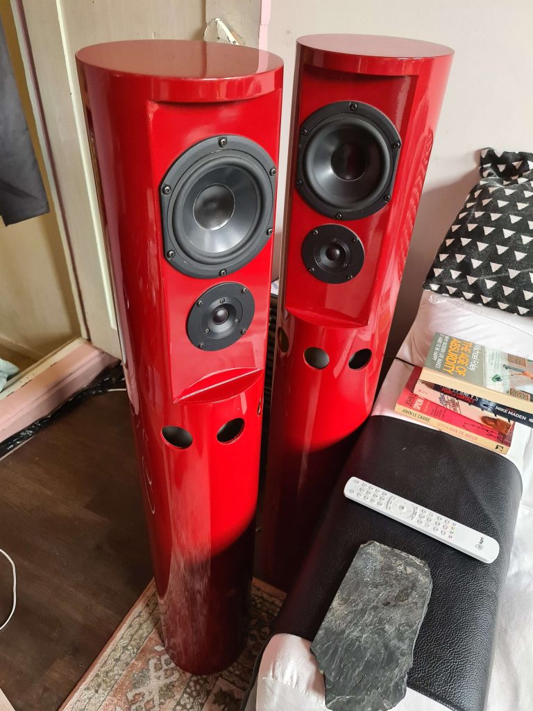
I received these flaming red specimens from a good friend of mine6the same one who has been of invaluable help in designing and building this entire system as he had been given them by his old electronics teacher, who in turn got rid of them due to his better half wanting them out of their living room (thank you!).
This teacher has built these himself out of gas mains tubing (of the under street sort), with an inner reflex tube, a passive crossover of some sort, and car paint.
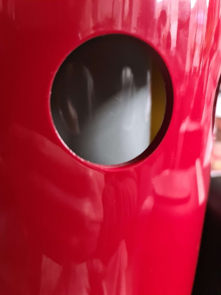
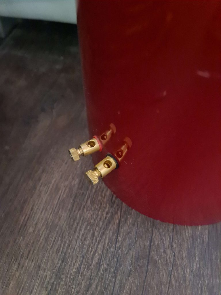
My friend, who was apparently there for some of that process, assures me they were calculated thoroughly and built properly, although he didn’t want them since they don’t quite fit the existing aesthetics of his room7I know right and he already had suitable speakers anyway.
I for one quite like their striking appearance, and the fact that they are made out of old gas mains, so I happily accepted them.
They have over the years picked up a few blemishes from repeatedly falling over (a minor flaw of their rather top heavy design), and their flat tops act as what Don Norman calls Affordances, meaning people kept putting things on top of them, or leaned on them with their arms while standing close by.
Given this rather increased their natural tendency to have a high velocity meeting with the floor, I’ve since placed decorative items on top of them so that the space there is already occupied and less enticing to any weary arms.
Now, at the time that I got them, while I had aspirations for higher quality playback (inspired by the system my friend was building at the time), I didn’t actually have an amplifier worth it’s salt, which resulted in my first DIY Audio Project:
The Amplinator 2000
After my friend had spent some time extolling the virtues, and then rejecting the thought of tube amps and chip amps, it was decided to build a known-good discrete Class-AB amp from plans made available by Rod Elliot over at Elliot Sound Products.
Specifically his plans for the ominously named Project 3A.8I appreciate the straight forward simplicity of just naming your projects “Project [Project-Number]”, but it does make it sound like some conniving cold war scheme designed to spread world socialism or something. But then again, I read too much
Class-AB was chosen because it’s much more efficient than a Class-A (with very little in the way of downsides when properly built that I could find, although HI-FI is a space with seemingly as many opinions on this as there are enthusiasts), and it uses less “mathematically correct voodoo magic” as Class-D amplifier tend to.9Class C was of course right out, as I’m not a radio receiver
(If you are not sure of what I mean by class here, this is perhaps not the article for you. There are plenty of good introductions to the technologies of audio reproduction out there and I don’t wish to duplicate the effort, sorry)
Now, Elliot very kindly provides in depth descriptions and diagrams of his circuits on his website, free of charge, which is great for people like me who might be able to build amplifiers like this but are still somewhat clueless when it comes to actually designing one.
But the Printed Circuit Board designs he keeps reserved, earning some bread by selling pre-made PCB’s trough his website.
That’s fine, but I10well, we, me and my friend wanted to use some non-standard components, and didn’t want to order a PCB from what quite literally amounts to the other side of the world, so this project turned into a nice bit of PCB design practice.
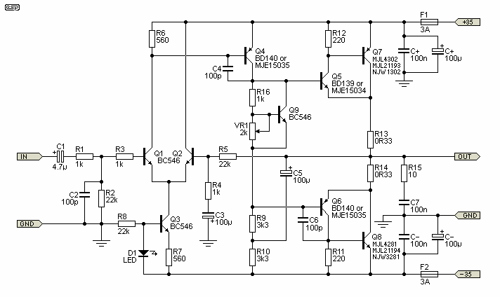

I’ll try not to bore you with the details of the PCB design itself, but I do wish to point out some relevant deviations, the main two being:
- The Size
- The PCB’s were designed in such a way that they are of the exact size of two pre-existing heat sinks (kindly donated by my friend), including matching of the pre-drilled and tapped holes already on there for mounting.
- The Q1 Q2 / T1 T2 phase splitting transistors
- These were replaced in their entirety by a dual-transistor package
- To be more specific, they were replaced by a Tesla11Not that one 12Nor that one KC-811 “NPN Transistor Pair for Differential Amplifiers” made by the good people in the former Socialist Federal Republic of Yugoslavia.
- Now, this was done because my friend had these laying around anyway (after having acquired them under unknown circumstances), and because it’s hard to get better temperature matching than with two transistors that are quite literally inside of the same package, which is (somewhat) important for the particular transistors it replaces.
- Also I really like having all my audio pass trough an obscure 40 year old part made for the glory of the motherland.13It’s always nice to be able to combine my interest in the cold war with my hobby electronics
- These were replaced in their entirety by a dual-transistor package

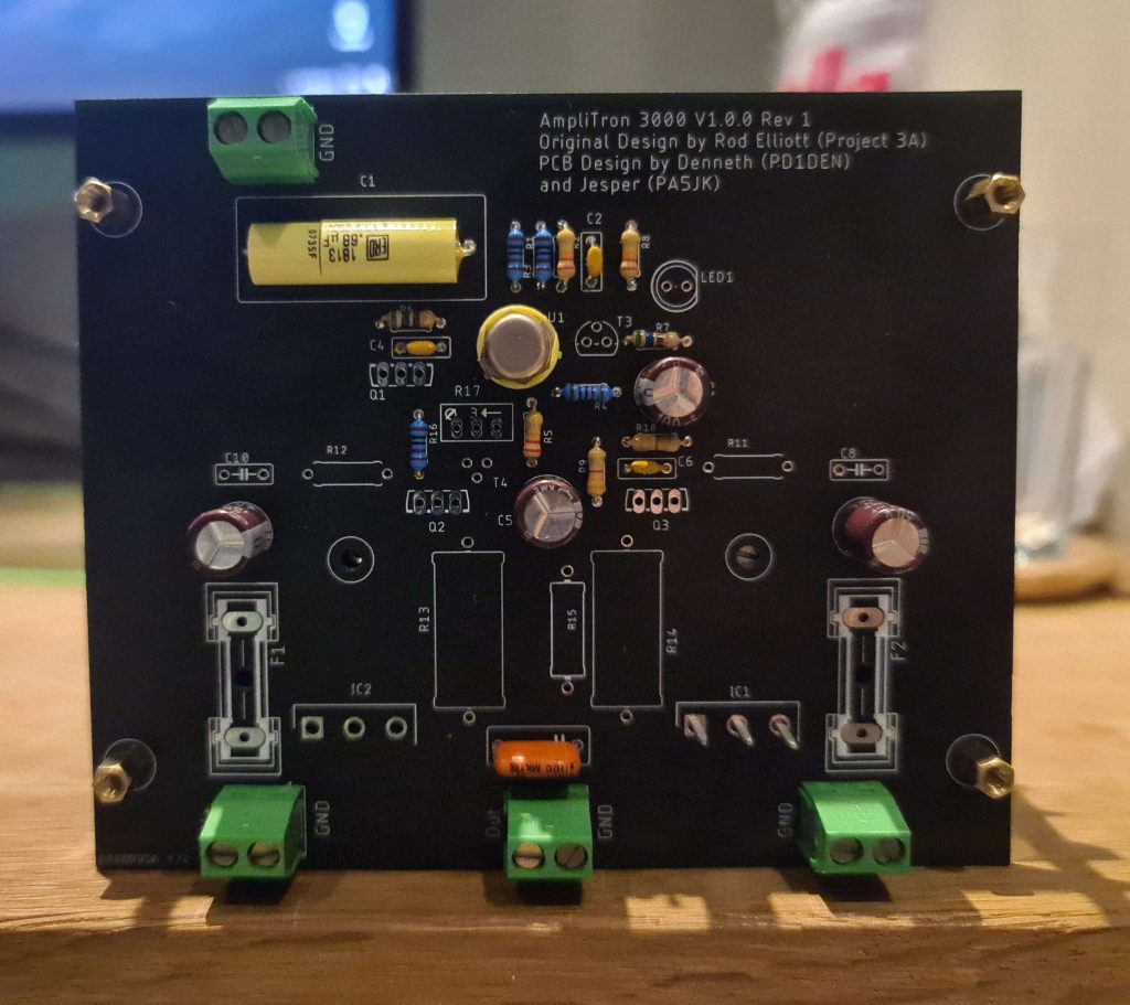
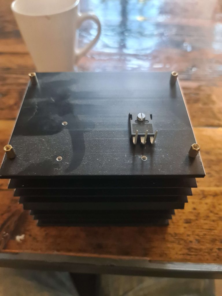

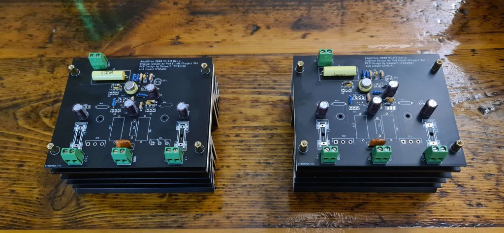


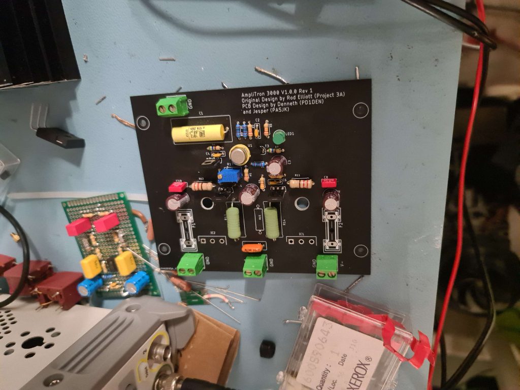

Now, two bare pcb’s and a toroidal do not an amplifier make.14well, not a good one anyway
What this project needed, was a box.
My friend, ever amazing, also had me covered on this, providing me with a rather unusual 3U rack mounted affair.
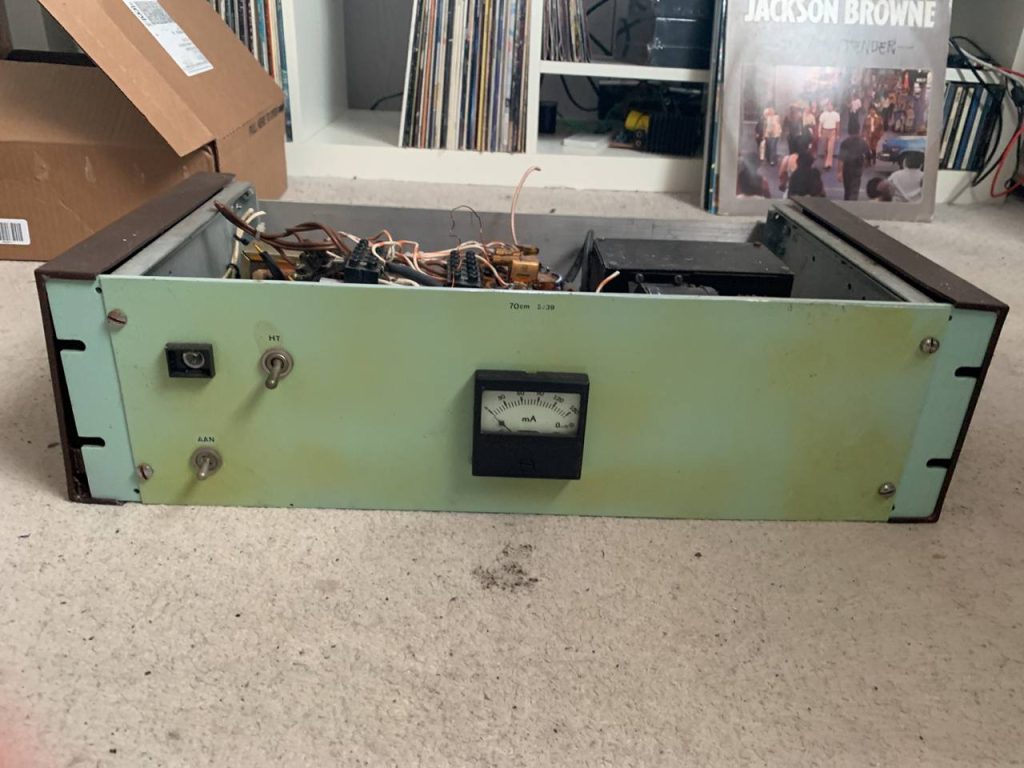
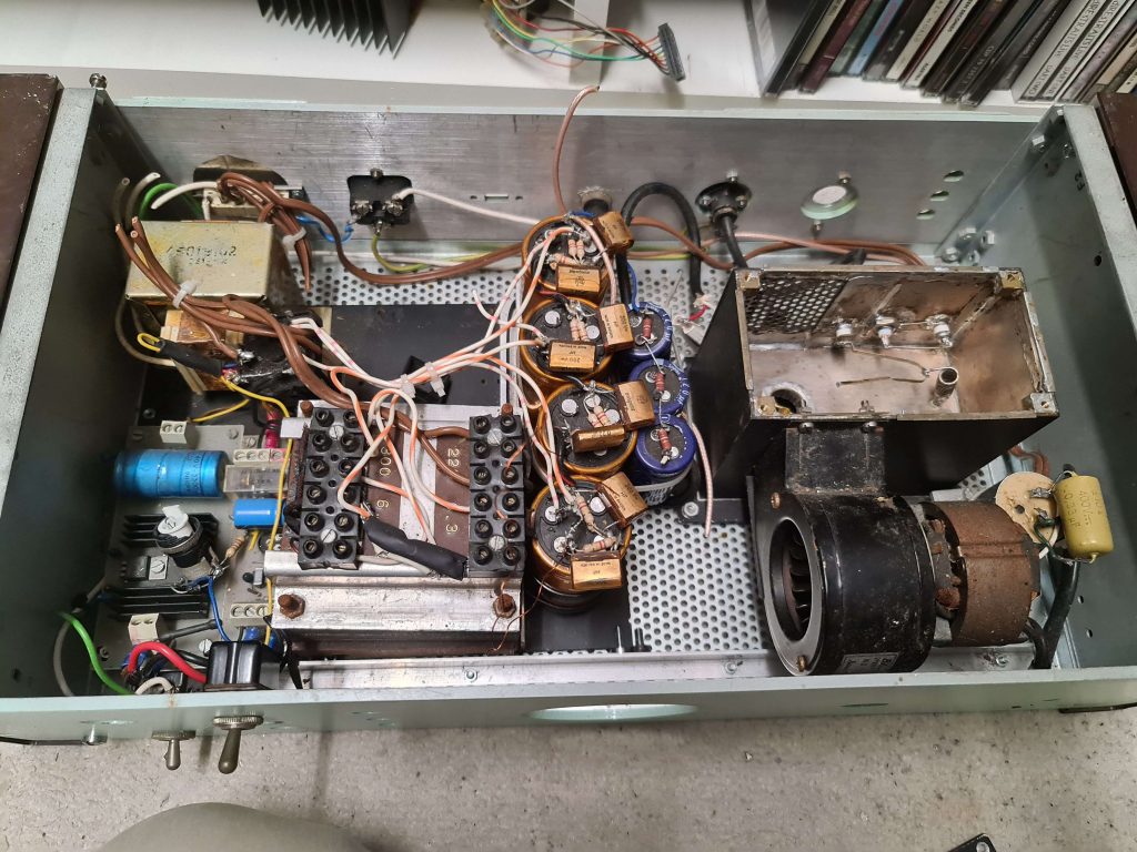
Shining a light on some of the newer paint on the back revealed covered lettering stating that this used to house an Ion Gauge Controller in a previous life.
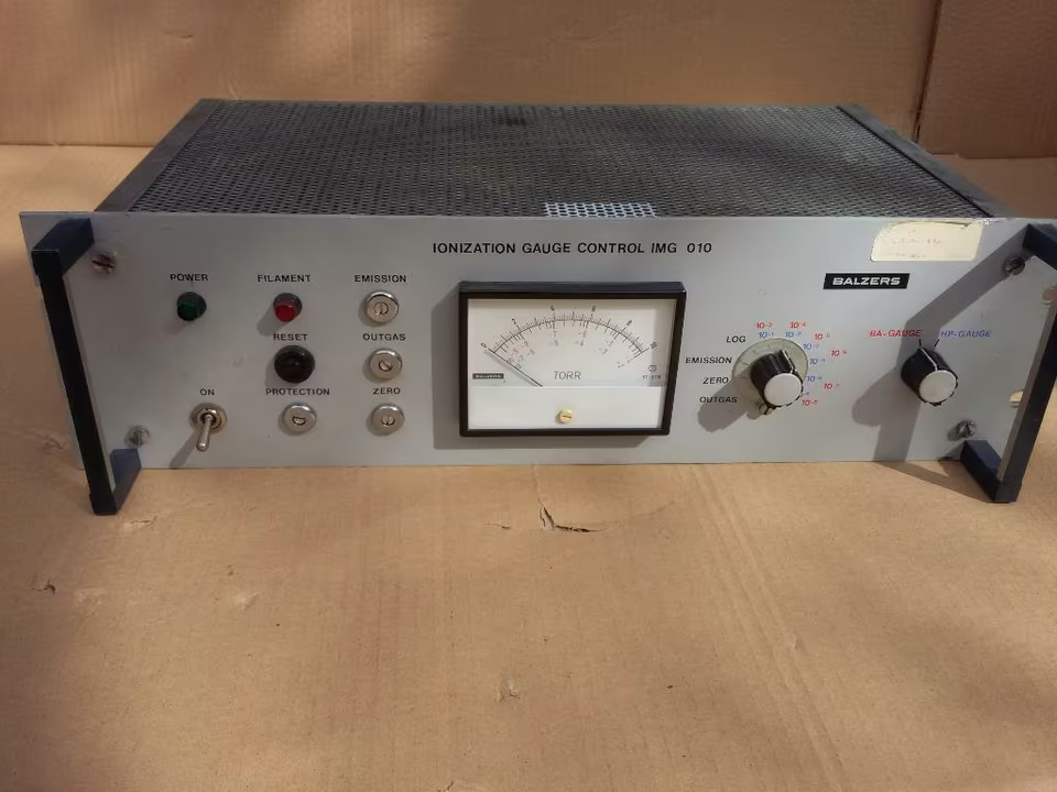
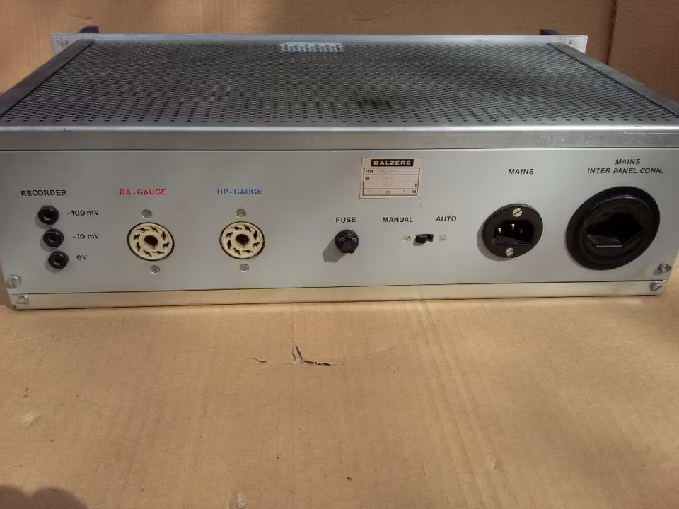
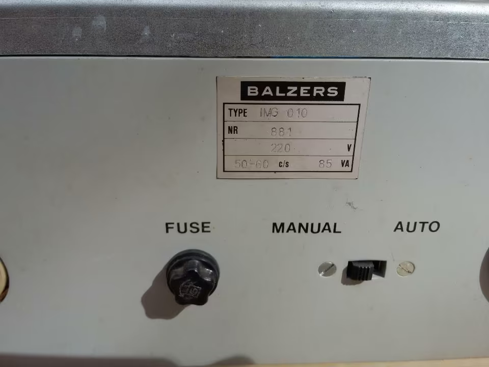
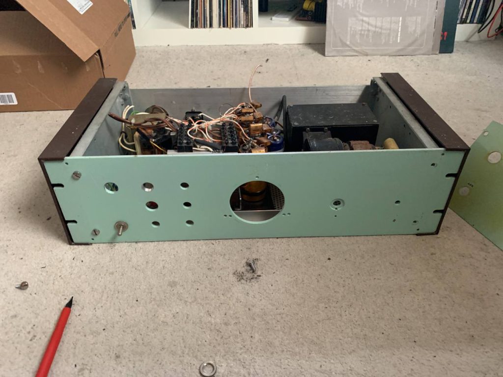
Somehow, this very specialized (and likely incredibly expensive) piece of lab grade test equipment ended up in the hands of a radio-amateur, who very neatly converted it into a rather powerful radio amplifier.
After the thing was no longer in use in their setup, he decided to donate it to his local amateur radio enthusiast club, where it was picked up by my friend, who immediately went to work gutting the poor thing for parts.
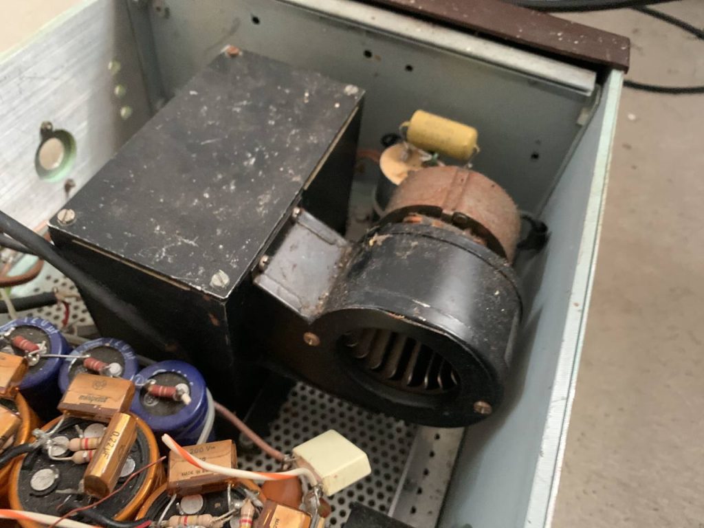
It even had a very neat home-made cooling and shielding box holding the high power vacuum-tube that was the star of the show, showing a rather ingenious active tension based contact method.


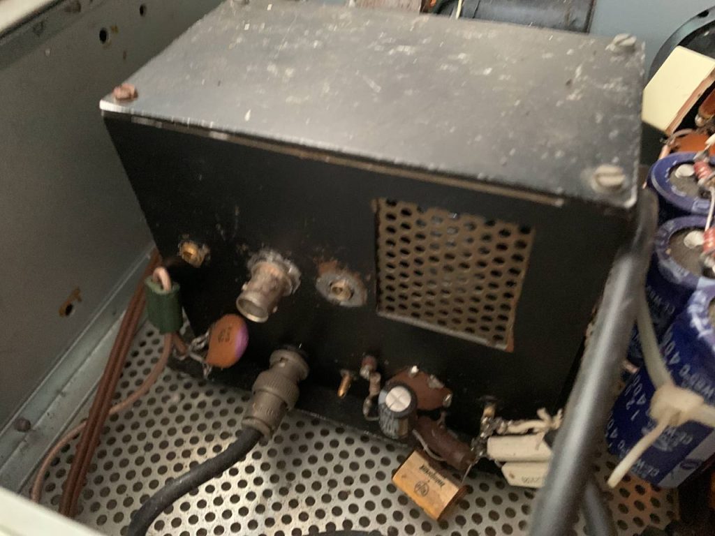
He had even made, from metal, cutouts that fit over the old connector openings to fit his custom design, and painted the whole thing a nice and calming seafoam green15or something along those lines 16If you’ve also noticed this peculiar green colour on the walls of old nuclear stations and inside of submarines, it turns out you can blame Faber Birren for that, who concluded and recommended that “light green” (now also sometimes called seafoam green or “vomit green”) is a nice, neutral, calming colour (hence it’s use in control rooms) incredibly unlikely to drive you stark raving mad if you’re locked in a room painted it (hence it’s use onboard submarines) for good measure.
Somewhere along it’s journey, it had lost it’s handle bars on the front, and possibly acquired two plastic handles to turn it from a rack mount device into a more freestanding unit.17I know and can find very little about the piece of measuring equipment this started out as, so I don’t know if these were stock from the factory / garage operation they came from, but do not see it on the pictures of the one that was for sale, although that might simply be because they were removed by whatever German laboratory wanted to mount it into some kind of rack arrangement
After my friend was done ripping out the entrails of a lovingly made (but superfluous) radio amplifier, we went to work installing my own two AmpliTron 2000’s18You may have noticed this naming on the PCB’s, even though the amplifier itself is called the “Amplinator 3000” as the title of this section implies. This is because I could not choose between AmpliTron and Amplinator for this project so I simply named the amplifiers themselves one and the whole unit the other.
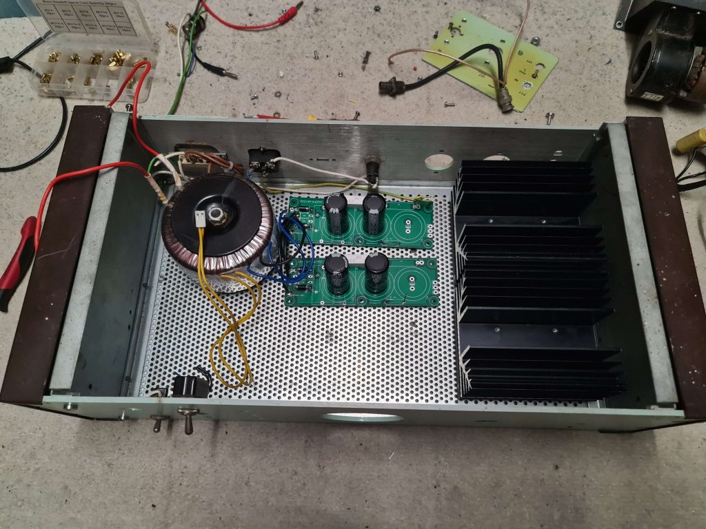

Note the change in orientation of the heatsinks.
This was done as putting them side to side proved to be restrictively tight, especially due to the incoming and outgoing screw connectors facing either a metal wall or another screw connector.
The resulting sideways orientation was chosen so the hot air could more easily rise upwards and escape trough the meshing, with the slight downside that the cover itself didn’t quite fit anymore due to the significant width (now height) of these units, although this has not impacted much of anything except my satisfaction.
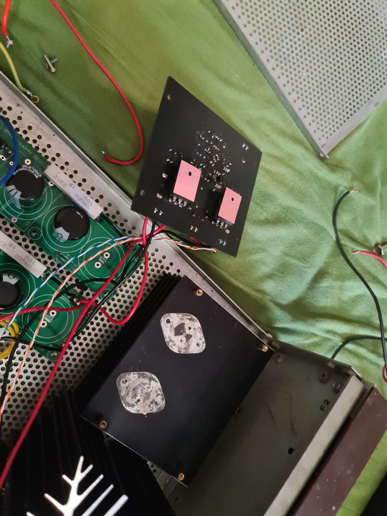


The amp in a temporary test setup as I was not going to wait until I was home and could hook it up to my speakers to hear it in action.
With the amp thus assembled, wired to my speakers, and hooked up to an appropriate audio source, sound was streaming into my room of a quality I had not experienced at my home before.
Hi-Fi, at that point, was achieved.
But of course I wasn’t done. True art is never done, only abandoned.19To paraphrase Leonardo da Vinci
Next I integrated a 4 input switching board to turn the thing into more of an integrated amplifier. As well as replacing the cheapo stereo potentiometer with a proper Alps (mainly for the more accurate Logarithmic response and channel balancing than anything).
And, of course, replacing the volume knob with the largest one I could find.
I also, more recently and in anticipation of mounting it inside The Rack, I ordered two handlebars with dimensions that seemed appropriate, and went to install those, as well as a (large) power indicator light as I kept forgetting to turn it off when leaving my room or going to bed.
The rack mounts themselves did not quite fit right, being off by something on the order of half a millimeter, meaning I could get the bolts in, just not more than partway.
I decided to push on regardless as mounting it without handlebars presents it’s own problems and the amount of bolt that would thread in seemed to be plenty for the application.
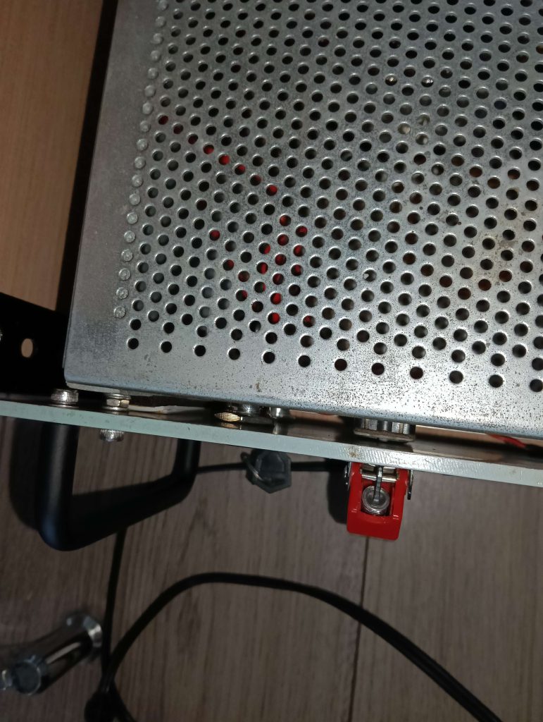
Unfortunately, the handlebars which I ordered (and the only ones I could find of the appropriate size) were meant for threading from the back of the unit, instead of trough the front of the bars themselves (as on the original), meaning my rather bulky bolts were too large to fit between the front plate and the main chassis.
I solved this rather crudely by applying spacers made from left over felt (as used underneath furniture to prevent scuffing) and double sided tape (stuck only to the felt, as this was purely a compressible spacer).
This seemed to work, and after a few weeks the amplifier has not decided to let go and fall out of my rack, so I’m considering this a success, although I cannot say I’m too happy with my imperfect “fix”.
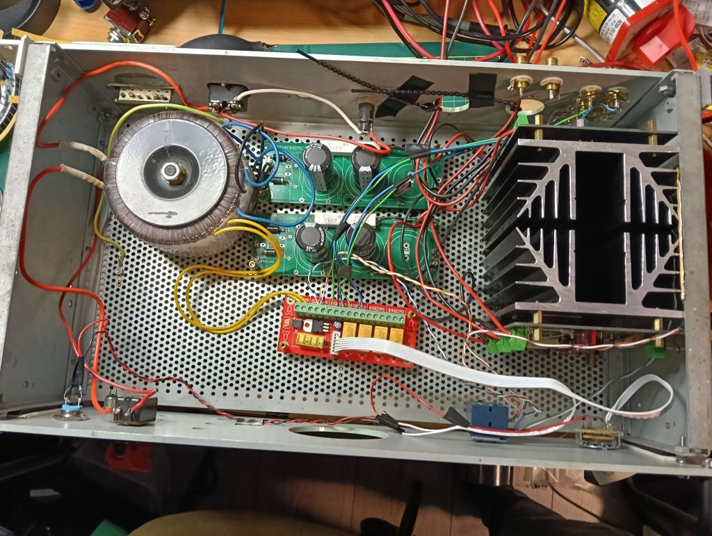
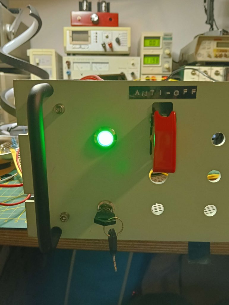
And the horrible things I did to get the thing mounted

This all being done, I mounted it onto the rack (quite an operation as I was doing this alone, involving misuse of an IKEA stool as well as a stack of old AV equipment being to prop it up (close) to the intended height).
In the future I plan to install a VU meter in the large cutout in the front, as well as some other minor upgrades (for example, this thing, I’m embarrassed t0 admit, does not currently have any fuses, as the PCB mounted fuseholders my friend ordered didn’t fit)
But already this has been the centerpiece of my Hi-Fi system, and is the electronics project I take the most pride in having made.
The total cost, for those interested, was about 200-250 bucks total, and according to people who have heard this who are familiar with some the more expensive offerings out there say it sounds like a 2000 euro pre-built Hi-Fi amplifier, which makes it more than good enough for my purposes.
The main downside of this amplifier, and it’s associated speakers, is that I have neighbors, and also a PC which is used often and which is not exactly in the optimal listening position.
So I also wanted to extend the world of Hi-Fi to my desk, hence my other amplifier project.
The Stopgap Dedicated Headphone Amplifier(‘s)
From the start, the plan has been to build a dedicated headphone amplifier following the same general principle as used for the Amplinator 10,000.
Find a suitable design on the internet, adapt it to a PCB, put it in a housing of some sort, and enjoy the music.
The design we chose was another Elliot Sound Products design, namely Project 113.
This progressed rather quickly, especially as we just completed the Amplinator 10,000 and the experience gained was still fresh.20This was approximately 4 years ago now
However, sadly, due to personal circumstances beyond my control, I was unable to finish the PCB design to the extent needed and it kind of fizzled out.
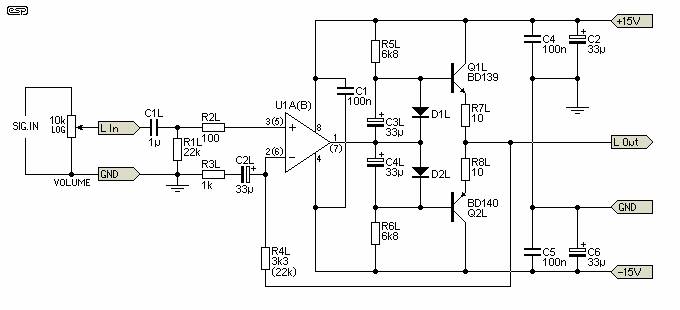


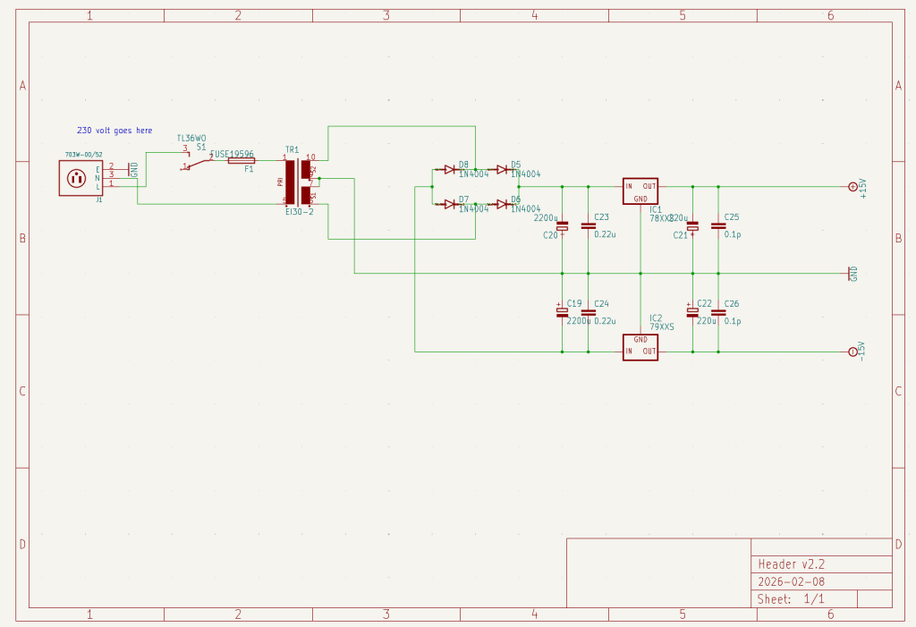

The main thing holding this project back is the 230 volt segment, where I could not find where to buy adequate PCB mounted parts, which is a small matter, but was enough to derail the entire project coupled with the aforementioned circumstances I was experiencing.
The thought behind the PCB mounting was that this whole PCB is supposed to slide into a housing I got from a friend, and trailing wires would be impractical, or at least less neat.
The current plan is to just use externalized wires anyway, with the added bonus that the power switch can then be mounted on the front, where I feel it belongs.
I’ll do a more detailed write up if and when I have actually produced this design.
But even though this design remained unfinished, my requirement for a nice sounding headphone set up still existed, so a stopgap solution was devised.
This started with finding, trough sheer luck, a pair of Sennheiser HD650‘s for multiple hundred euro’s below it’s then market value, new, in a high end audio store across the country.
Given this opportunity, I pounced on it and before long had a pair in my possession, the very same ones I’m wearing as I am typing this.
While not as good as my full on speaker + amplinator setup, if only because of the inherent limitations of headphones when it comes to lower frequencies, they still blast all other headphones I’ve ever owned (and all but two that I’ve ever used) out of the water, and whenever listening trough my speakers has not been practical these have provided excellent sound to my expectant ears.
But, with these being high-impedence (300Ω as opposed to the more usual 16Ω), I wanted a dedicated amplifier.
The stopgap proposed by my friend, which also solved the problem of providing phantom power to the new microphone I received, was getting a second hand Focusrite Scarlett Solo (2nd generation) for 50 bucks.
This I did, and after one train based trip to Amsterdam later to pick it (and a free microphone mount) up I was set.
My then roommate kindly 3D printed a nice mounting bracket for it, and it’s been living like that under my desk for the past few years now.
//this segment needs more pictures, which I plan to dig up from the archives at a later date
However, with the advent of my Great Controller project, and it’s associated Patch Panel (more on that later), I really wanted a pair of headphone amplifier that had an RCA input so I could drive it from the same sources as I was / am using for my main Amplinator setup.
I also had enough of the Scarlett Solo disconnecting for a moment now and then when a colocated mini-fridge shut off it’s compressor, the EMF from which overwhelming the USB connection for a split second, which meant it had to be manually disconnected and reconnected (producing some loud pops on my headphones every time) before it wanted to continue playing.
So, in the spirit of putting a bandaid on a bandaid, I found and ordered a cheap (10 euro) dedicated headphone amplifier board off of a reputable DIY-HIFI parts retailer, as well as receiving a spare 12-0-12 V transformer from my often mentioned friend.
The Amplifier itself is a HA-PRO2, about which very little is known.
For those curious about it’s function, who can also read schematics, a pair of schematics were very nicely reverse engineered by a certain Paul Schmidt, which I found while looking into this board.
I found them here, but decided to also host them on this website as duplication promotes preservation.
As a knowledgeable reader might recognize, this is an incredibly straight forward op-amp based circuit, with a small aside to provide a timed muting circuit to keep out any startup transients.
The board, after I ordered it, came pre-assembled, and needed only to be hooked up to a proper transformer and some audio inputs.
Because I have very limited experience with 230V, and I am rather paranoid, I first 3D printed a rather overengineered case to try and keep the mains and the everything-else as separated as I could.
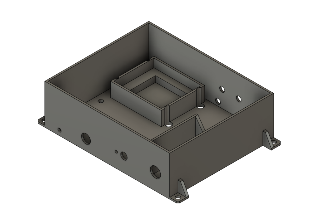
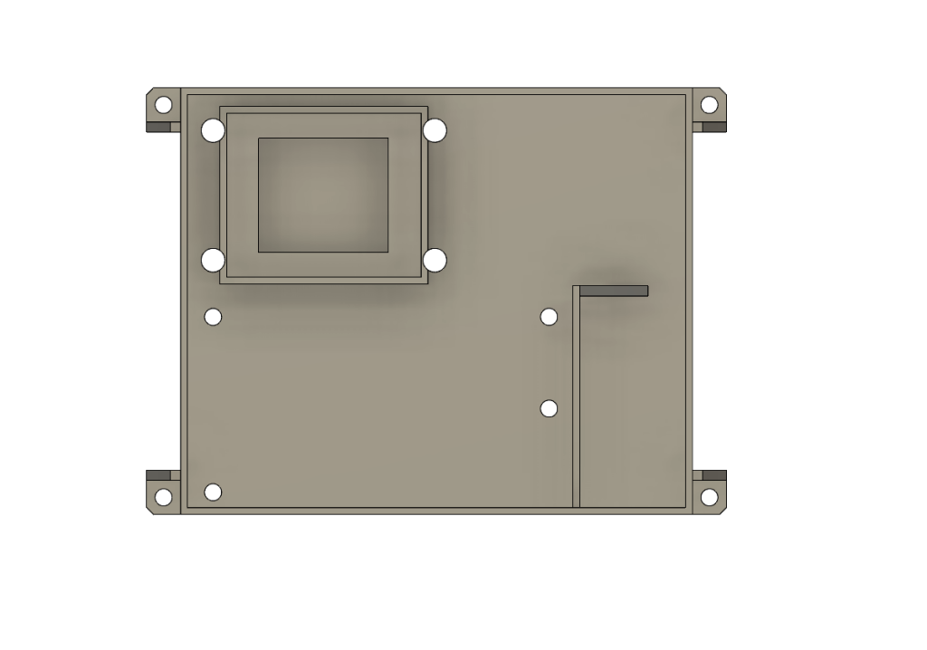

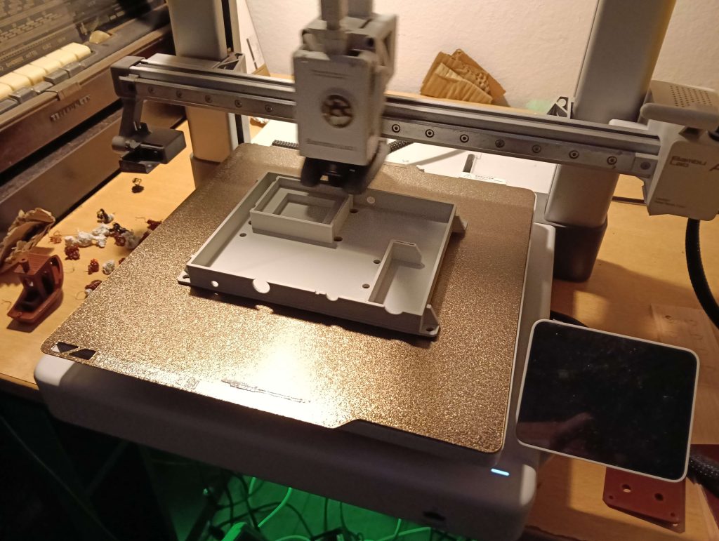
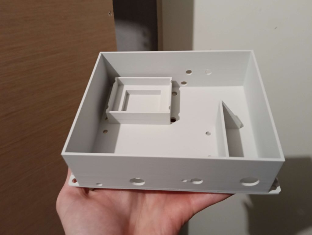
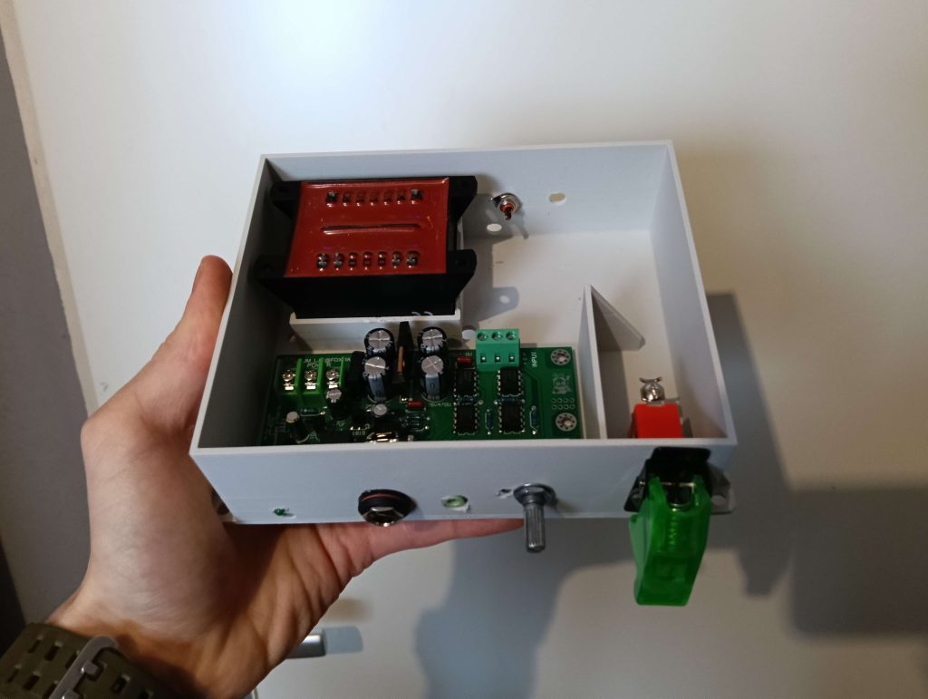
Now, as it had been a few years since I did any significant CAD work (due to those aforementioned circumstances again), so I made a few rather rookie mistakes.
For one, I failed to take into account the fact that I needed some space between the bottom of the PCB and the bottom of the case due to the pins sticking out.
Since this case took about 125 grams of filament to print (about 1/8th’s of a fresh spool), and I didn’t have much of the light-gray filament left, I made the decision to just make the holes fit using the careful application of a drill and some filing, as this is only supposed to tide me over until I can build my Project 113 clone anyway.
Next I installed the circuitry, which seemed straightforward enough.
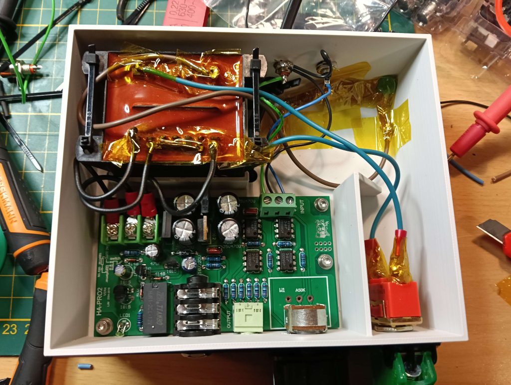
It also seemed like something that would adhere better to the flat surfaces (such as the contacts on the transformer) than regular electrical tape, and since I suspected I might have to remove it I would rather deal with the rather forgiving Kapton Adhesive21which, interestingly, smells strongly of honey than the sticky goop all electrical tape seems to exude. (this turned out to be a good call)
After wiring it all up, turning on the power (stopping to check if anything started smoking or became unproductively hot), and connecting it up to a source and my treasured headphones…
It didn’t work.
Taking it back to the bench, I could not find a clear fault (“Everything’s connected but nothing’s working!”22Quoted from Asteroid City (2023), although it’s probably been said before and since), but after some back and forth with my friend (still the same one!), removing the switch, measuring and remeasuring voltage and resistance at various points, and eventually some telephonic consultation, we were able to find the fault.
I was not consulting the schematic I had posted above during the construction, which would have saved me this particular headache, but on the board’s silkscreen itself was printed how the transformer and power switch should be wired in, and this includes an RC snubber.

Now, I have basically only worked with small scale, 12 volt DC circuits before this, so while I’ve found out the hard way what flyback diodes are used for, I had not yet encountered an RC snubber.
First I had to find the parts for that, since 1 watt resistors and 1KV tolerant caps are not things I have parts bins full of.
A box of an unsorted assortment of electronics junk my friend had kindly donated some time before came to the rescue here, even if it did take literal hours of sifting and sorting.

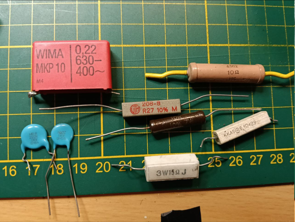
Now, the problem lay not in faulty components, or a broken transformer, or anything of the sort.
It was, as is so often the case, “Operator Error”.
In this case, I had interpreted the cramped schematic on the silkscreen as follows:
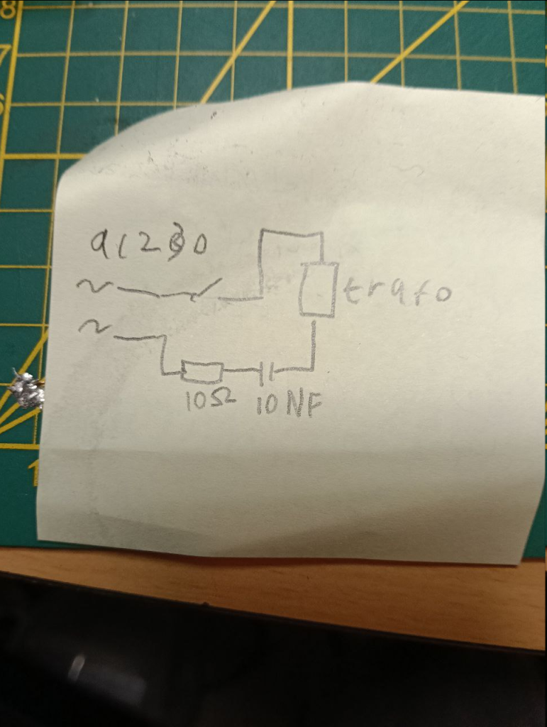
When it should have been wired up like so:
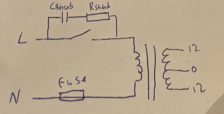
Looking back, this is an incredibly stupid mistake, and one caused not only by my lack of experience with mains circuitry, but also a complete lack of independent thought (a capacitor blocks alternating current, I am trying to conduct alternating current…).
But, the fault was found, and after relocating the snubber circuit to the right place, the thing started working.


I did still want to print a lid though, as exposed 230V wiring is not something I want anywhere, let alone on my desk.


I tried printing this out of what was left of the same spool of light-gray PLA I used to print the case itself, but trapped moisture nixed that plan (this filament has been kicking around for years in attics and sheds during those legendary circumstances I was experiencing, and especially when trying to print something large and flat the moisture it can absorb in those kinds of environments becomes a problem)
Since I did not want to triple the costs of the entire amp by buying a 20 euro spool of light grey filament just to finish the top, and I didn’t want to spend time improvising some kind of drying solution for the light grey either, I simply accepted the top was not going to match the bottom (this is just a temporary amplifier, after all), and decided that I might as well print it in a fun colour if it’s not going to be matching anyway.
I settled on translucent orange, of which I have almost a full spool still kicking around since I bought it (and so far, had only used it) for the tail end of Perigee-2, to aid in recovery.
If I’m ever going to use up that spool I’ll have to start using it, and this is a nice and loud colour to contrast the light grey (and the translucence also happens to nicely match the mildly garish translucent green switch cover I had added for some extra razzmatazz).
I think it turned out surprisingly well.
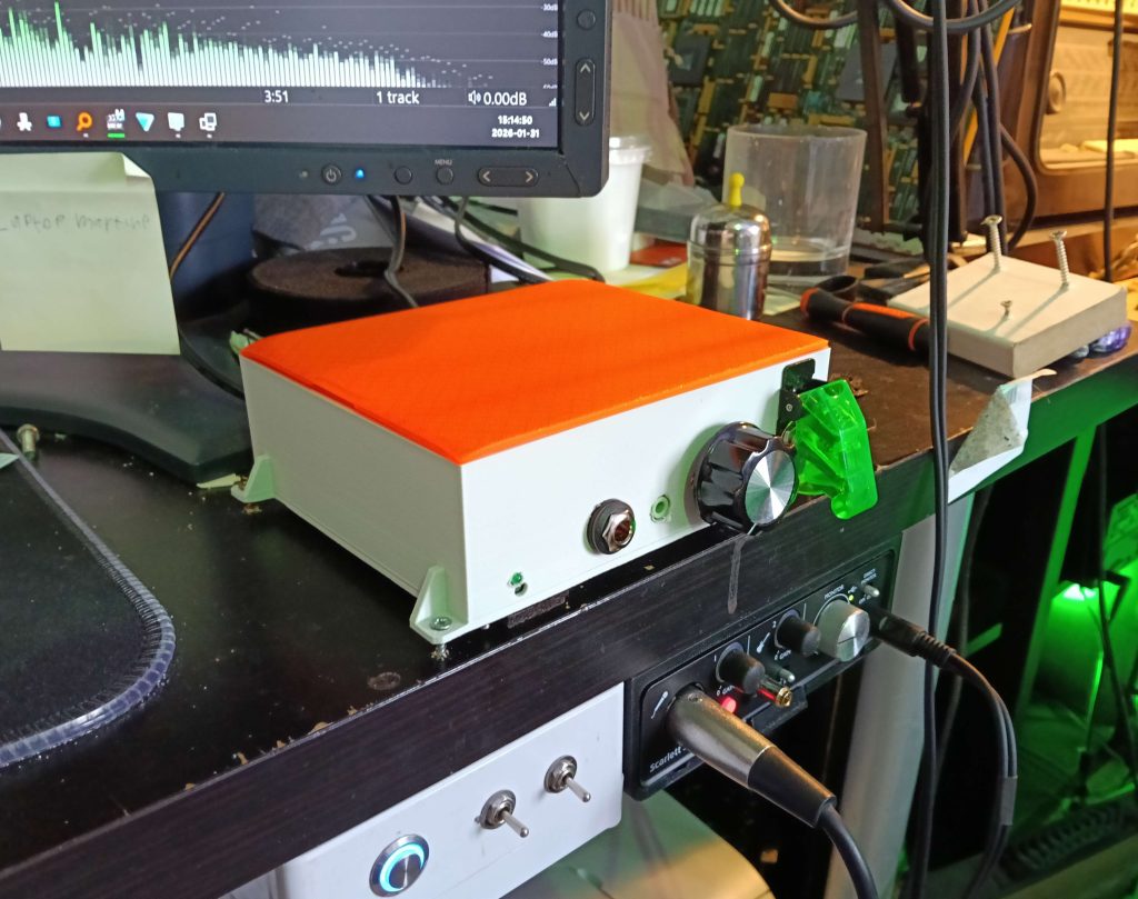
Note also the gap between the amplifier and my desk.
This is due to the mounting bolts of the main board, as well as the tie wraps that are keeping the transformer in place, both of which stick out on the underside.
As I didn’t want to increase the complexity of the actual housing to simplify printing, I simply added a double layer of the same furniture felt I used as spacers for my Amplinator 10,000, which provided enough clearance that no stress is put on the PCB.
The main problem after all of this was done however, was that the thing simply worked way too well!
For a normal listening volume I would have to turn the volume down so much one channel would start fading out as the potentiometer was basically at it’s endstop.
My friend, who has worked with opamps much more than I have, recommended putting a 2.2K Resistor over top R5 and R7, which control the gain of the main buffer opamp.
Putting it over top reduces the total resistance (thereby reducing gain), and meant I didn’t have to take the whole thing apart and try to de-solder the existing 10K either.
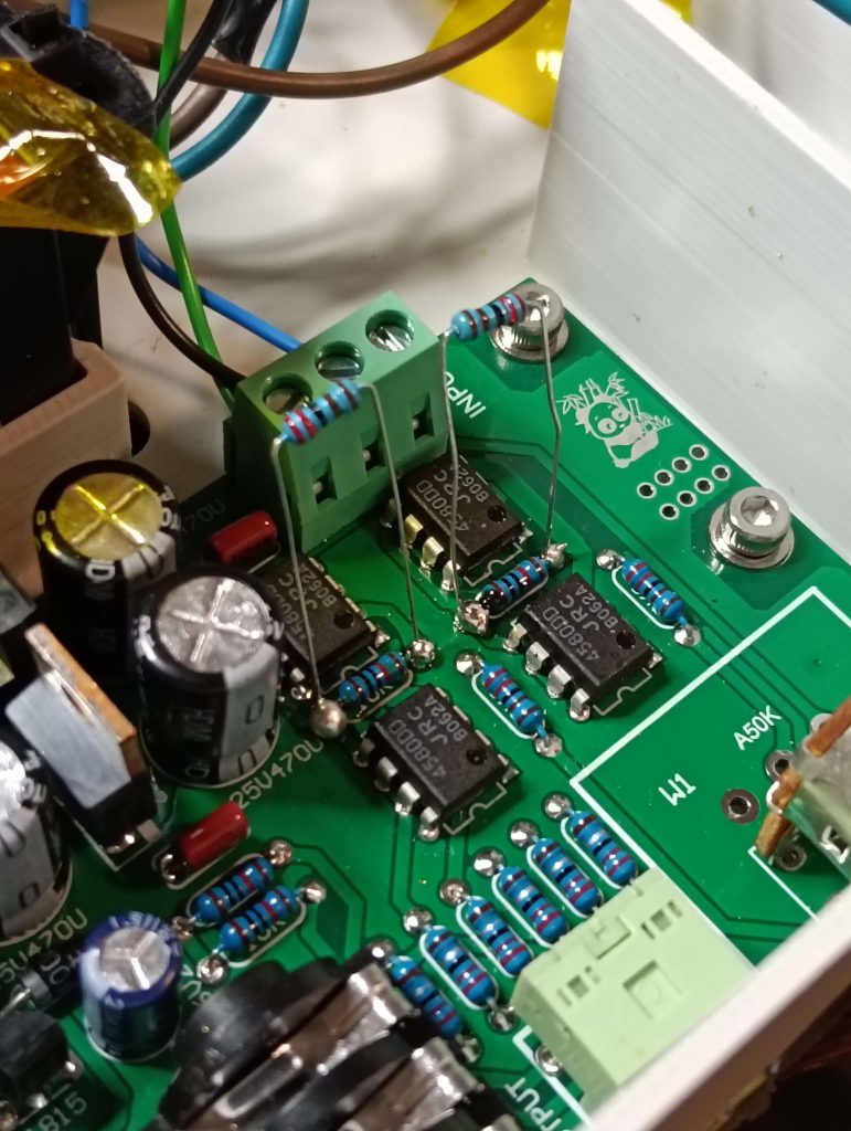
However, when playing from a straight CD source it was still on the loud side, at least for me.
So in the spirit of putting a bandaid on a bandaid on a bandaid on a bandaid24I was really looking forward to being able to reference this video, it’s great, I simply soldered yet another 2.2K resistor over top of the already janky 2.2K resistor, reducing the gain yet again, and saving me from the trouble of replacing the old 2.2K with a 1K.
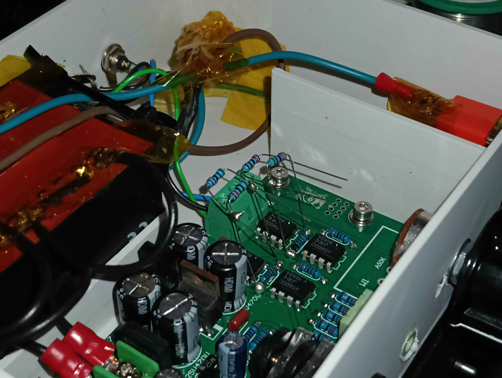
“There’s nothing more permanent than a temporary solution”
I’m using it right now while typing this, and there is definitely a noticeable difference between this and the Focusrite, when it comes to clarity and seperation (both stereo and soundscape).
Whether that is due to the quality of the amp itself, due to the usage of my external DAC, or just placebo, I do not know, but I’m very happy with this solution.
“But how is this connected to the DAC? I thought the Amplinator was already connected onto there”, asks the hypothetical reader.
Well, that’s because there’s another elements in the audio path between these amplifiers and their sources, and that is:
The Patch Panel
Now, I know I’ve used the word (abbreviation?) Hi-Fi in this article, it’s even in the darn title.
I also know that it is usually considered good practice to have as little between your source and your amplifier as possible, as anything in the signal path (connectors, cabling, switches) is liable to alter or otherwise distort the audio in some unwanted way (although I do think rhodium plating and the like is taking things a little far)
However, while I can definitely see the logic, and believe this can most definitely be the case, I also think that’s really boring.
I want arbitrary audio connections, I want obtuse and circumspect audio routing, I want to make weird and unusual topologies and I don’t want to get behind my system on my knees every time I want to wire something up differently.
Hence, the patch panel.
Now I promised myself when conceiving of this that if I heard a difference in the audio quality after messing with my signal path like this I would forgo it and just stick to normal DAC –> Amp connections like the rest, as this is not something I want to sacrifice the practical quality of my system for.
After having built it, I do not hear any difference in quality whatsoever, and am having way more fun patching and switching and in general just messing with my audio system in interesting ways, easily and regularly.
With that disclaimer out of the way, let’s proceed.
The original concept of this came about when I was very generously gifted a high quality reel to reel tape machine, and was setting about recording some of my favourite music to tape, which involved changing my cabling to wire my DAC up to the inputs, and then wiring the outputs up to my amplifier (which was previously connected to the DAC).
And then, of course, having to undo all of this when I wanted to listen to a CD instead of a tape.
This is of course part of the reason I have multiple inputs on my amplifier, but I desired independent control, especially as I was also frustrated I could not listen to my tapes trough my headphones (for example), rather limiting the machine’s utility.25While tape and recording to it is of course something I’m mainly doing for fun, I do think it’s useful to have a high quality audio source that does not require my PC to be on and that does not easily support changing what music / track I’m listening to, as things like reading and studying often suffer from the paralyzing selection of music I can switch between, not to mention the distracting power of an ordinary computer. Also the spools spin round and round and that’s very enjoyable.
So, taking inspiration from both Patch Panels found in mixing rooms, as well as old telephone exchanges, I set about to build a patch panel, as an inaugural module for my new rack (something preventing me from building it earlier was a lack of sturdy mounting options that could fit my regular audio “stack”, as I feel most housings I might have used would have had a tendency to shift when plugging things in and such).
I chose 6.35 mm (1/4 Inch) Stereo Jacks, for a number of reasons.
- They are what are used in (lots of) professional patch panels used in the music and entertainment industry.
- Compared to 3.5mm jacks, they are far less dainty, and more satisfying to use.
- Compared to RCA Cinch connectors, this is only one connector / cable per Stereo Pair.
- Pre-made cables are available in short lengths already, meaning I don’t have to make them myself (which I feel would have been a precursor to faulty connectors, and would heavily limit my colour options)
In anticipation of building the rack, I ordered 50 Rean RJ3VM Chassis Mount Jacks from a specialist guitar part supplier in Germany (I believe these would normally be used for “Stomp Boxes” used to provide effects for electric guitars).
This type is very compact, making my rows and rows of them easier to achieve neatly, and by ordering 50 I got to take advantage of bulk discounts, as well as having enough for any future expansions as well as spares.
I was also able to acquire 12 coloured 60cm patch cables, also intended for Stomp Boxes.
When the rack itself was completed, I first built a proof of concept to see if this idea held up in practice.
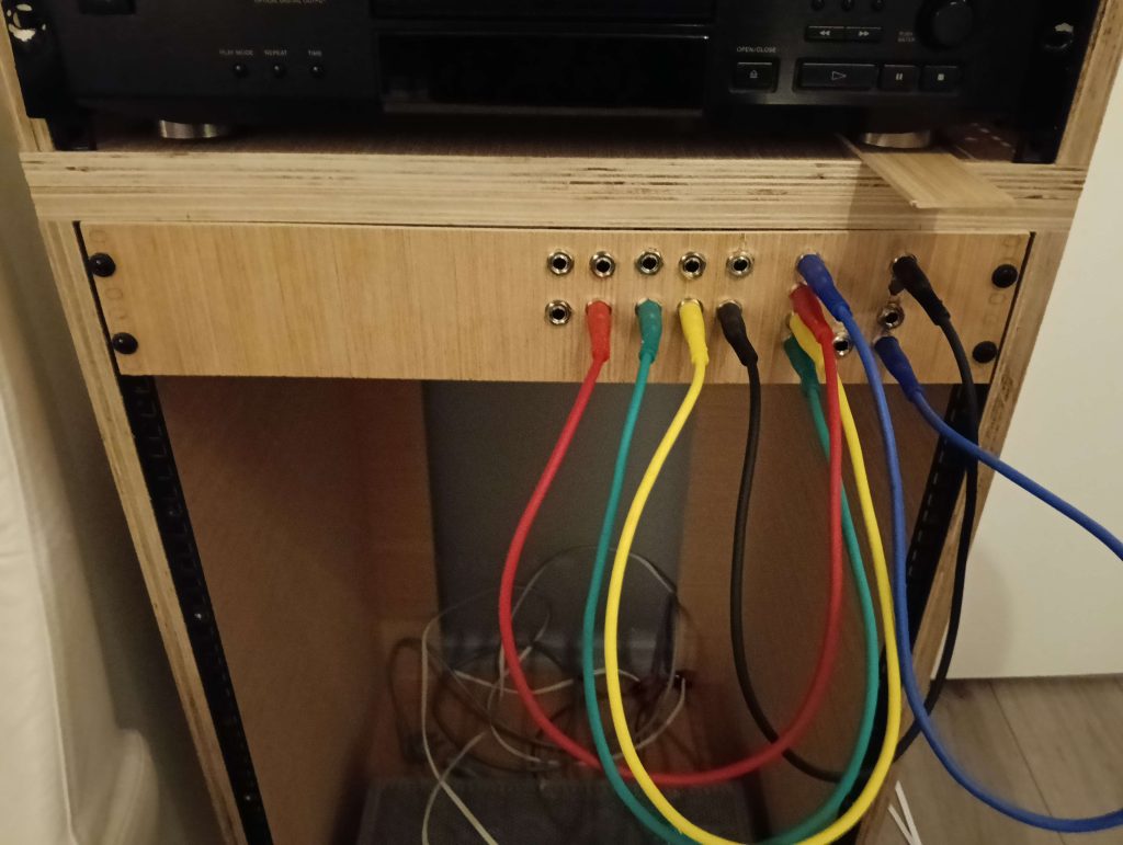
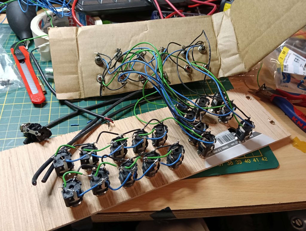
Yes, that is cardboard, I did not have the A1 Printer yet (nor the 3mm drill bit I needed to mount a plate using standoffs) and I merely wanted to test if this could actually work.
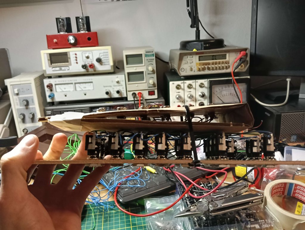
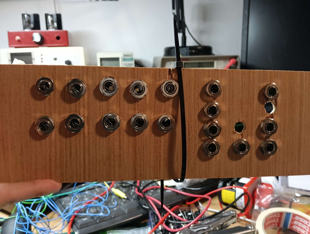
The holes not populated with jacks are that way because they are too close to existing holes and so the jacks don’t fit; I am terrible at working wood.
Notice how the panel has flipped. with the jacks now being on the left. This was due to concerns the cables would interfere with use of the Amplinator 10,000 volume knob if hanging from the right side.
Now, the idea was to have outputs on one side (DAC, CD, R2R Tape, Cassette etc), recording inputs, where applicable, next to the appropriate output (R2R input, Cassette Input), and then a row of inputs (Amplinator 10,000 Channels, the visualization modules, and the headphone amplifier).
The two rows of five jacks each you see next to the main cluster are simply linked up, and used to combine multiple audio signals (for example, to take the output of my DAC, and feed it to both the Amplinator 10,000, as well as the two visualization modules.
This was done as I wanted a system where I could change what source was being used (for example, going from DAC to Tape), and still being able to use the visualization components (which would normally be hardwired between two devices in a pass-trough configuration)

Note the rack mounted “headphone holder” which I am using to hold unused cables.
After proving the principle, and acquiring a 3mm drill so I could mount M3 bolts onto the wooden panels I am using as test beds, I designed and 3D printed an RCA holder (to save myself having to drill into wood), which could then be mounted using standoffs behind the jacks.

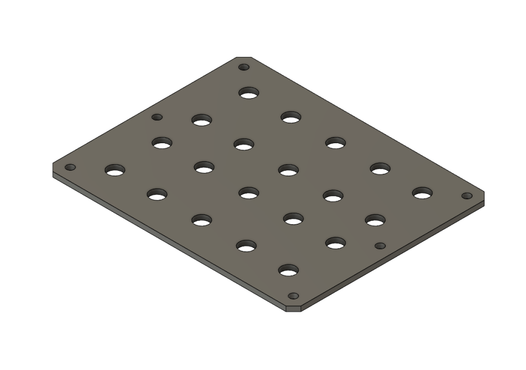

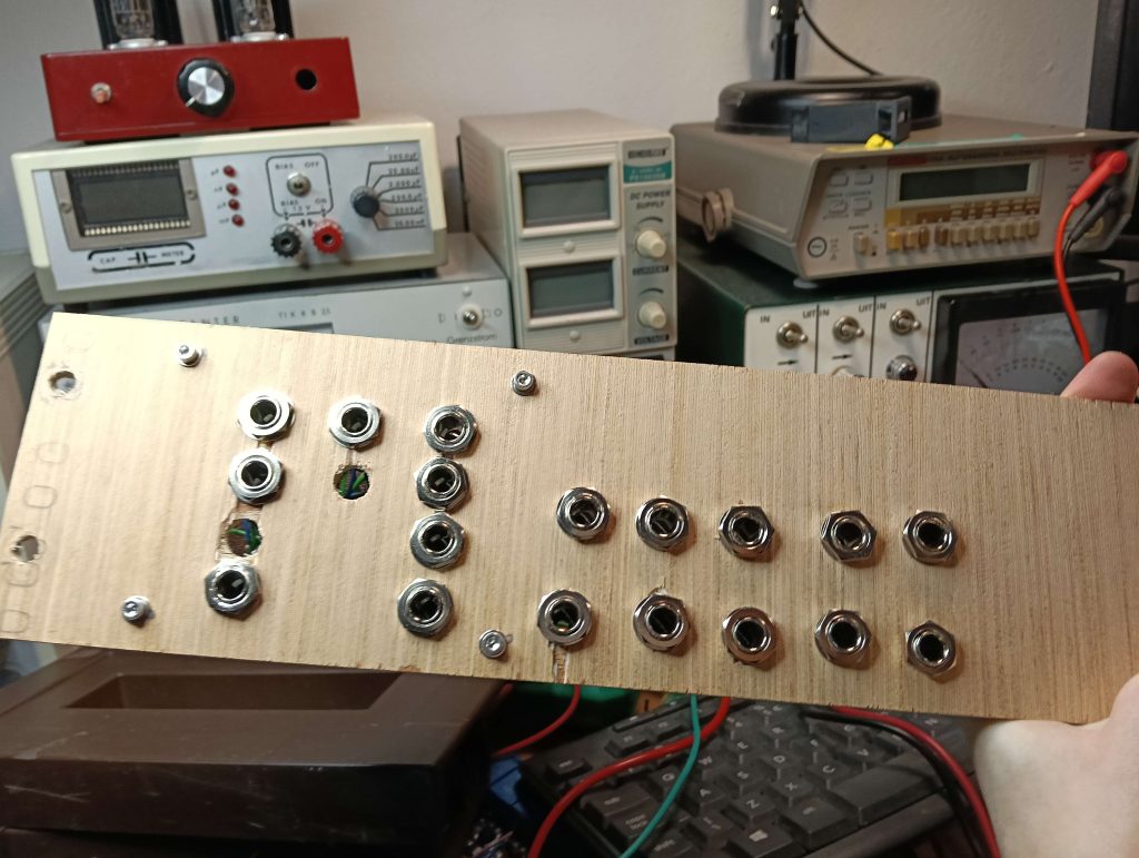
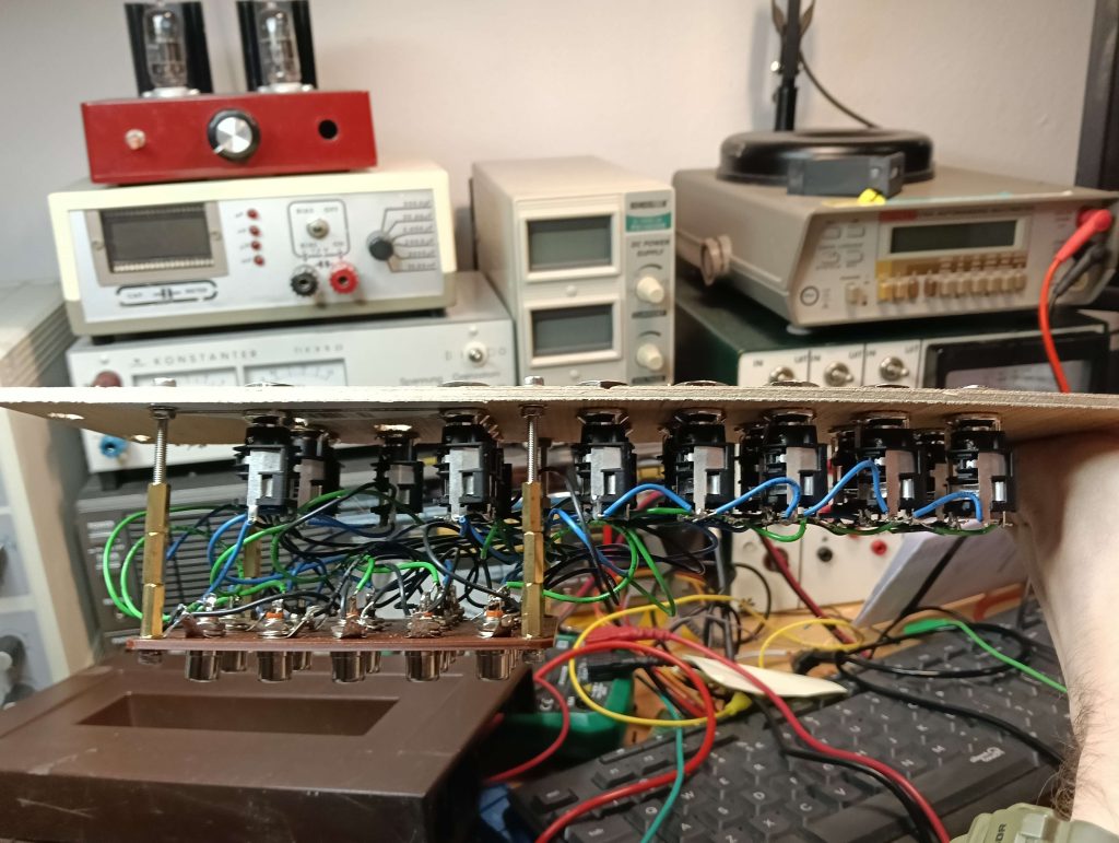
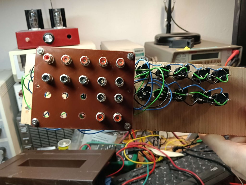
I wasn’t done with this abomination though.
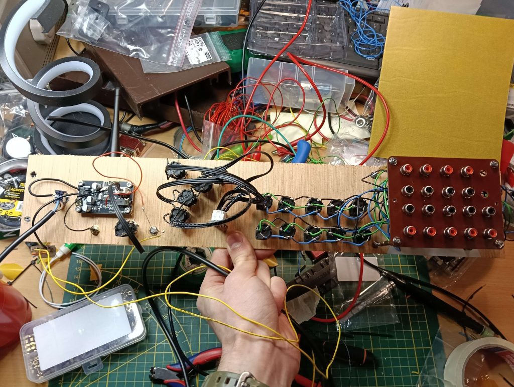
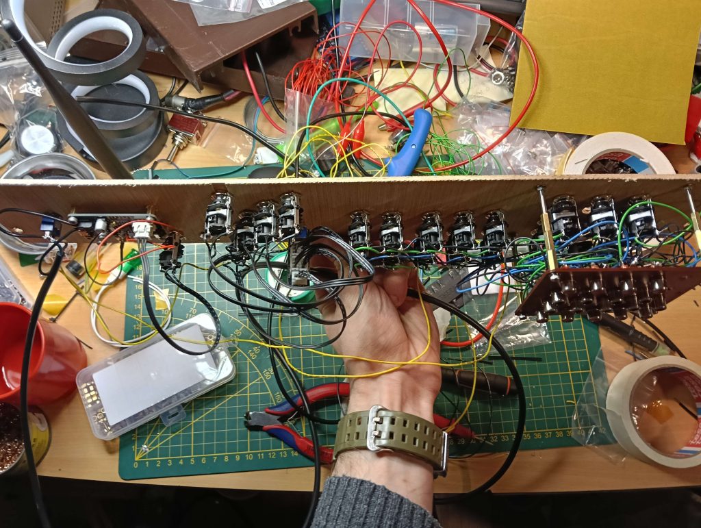
On the left there is a cheap Bluetooth board added as an experiment (the idea was to provide guests with an easy, if lossy, way to play their own audio trough my system, but the board sounds very very bad and is not used at the moment).
In the middle is a very simple 4 channel switcher (to be replaced with a 4 channel relay board sometime soon26A word with a very imprecise meaning…), to provide more flexibility when it comes to changing the signal source without changing the wiring (this panel is supposed to be entertaining, not a chore).
Future plans include a potentiometer for arbitrary volume control, a zero gain buffer, an audio source that just plays elevator music 24/7, and more.
The great fun of this design (up to and including the crappy wooden construction), is the infinite flexibility.
If I want to add an input for my newly constructed headphone amplifier, or mess around with a 4 channel switch for signal routing, or anything, all I have to do is take off 4 screws, drill some holes, solder some wires, and put it back in.
Oh, and take out / put back in the 8 RCA Pairs wired into the back, but that’s a small price to pay.
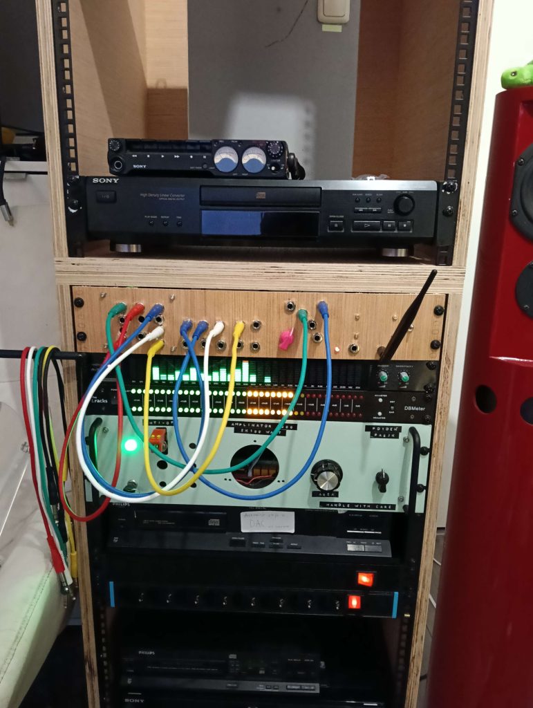
I am aware of the amount of Hi-Fi good practice that I’m ignoring here in my pursuit of the whimsical, but I have quite literally not been able to tell the difference28I will admit I have not performed any blind A/B tests, but as I (and also seemingly anyone else) cannot hear the difference in a blind A/B test between a 128kbs mp3 and a lossless FLAC either I am not too worried 29For those who wish to claim “Golden Ears”, I refer you to this article., and besides, if there was a cost effective method to switch the audio signals arbitrarily using relays instead of passing it trough wires, I would be doing that.
I use it daily when switching between listening to FLAC’s on my PC using my headphones, and listening to CD’s trough my speakers.
And, when I wish to listen to a Tape, it’s incredibly easy to patch that in instead of the DAC.
Speaking of which:
The DAC
My friend, with whom practically no part of this audio setup would have happened, builds DAC’s for fun.
Specifically, he salvages old, cheap, second hand Philips CD player30From the very first wave of CD players, meaning around the mid 80’s for their DAC chips, which he then transplants onto custom built PCB’s.
These were the first Digital to Analog converters ever put into mass produced consumer grade devices [citation needed], long before ΔΣ types became practical. This meant they were using an array of precision laser trimmed resistors in a ladder configuration to instantly and directly produce the appropriate voltage from the input audio bit.
He claims that these are better than even modern ΔΣ DAC’s, mainly as there is no negative feedback (which in ΔΣ’s inherently adds some lag to sharp rises and falls, as it is an integrating system, hence the name).
Since an old CD player like this is only about 10 bucks, and relatively easy to modify into an externally driven DAC, this seemed worth a shot.
So I bought myself one, and set to work on modifying it (again under expert council of my friend).
First came a Non-Oversampling modification.
Due to harmonics, all CD players require a pretty steep filter to prevent a multiple of the Nyquist Frequency from leaking out into the world.
Usually, to make this filter less harmful to the sound (and less expensive to construct), an oversampling stage moves the harmonic further out of the audio spectrum, where it can be gotten rid of by a more gradual filter.
Now this is not really my field, and I can’t say I understand this all fully, but the filtering included with the Non-Oversampling did seem to make the sound a little tinny, so I performed the specified modifications by removing it.
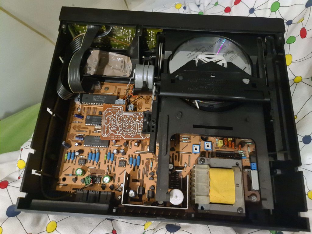
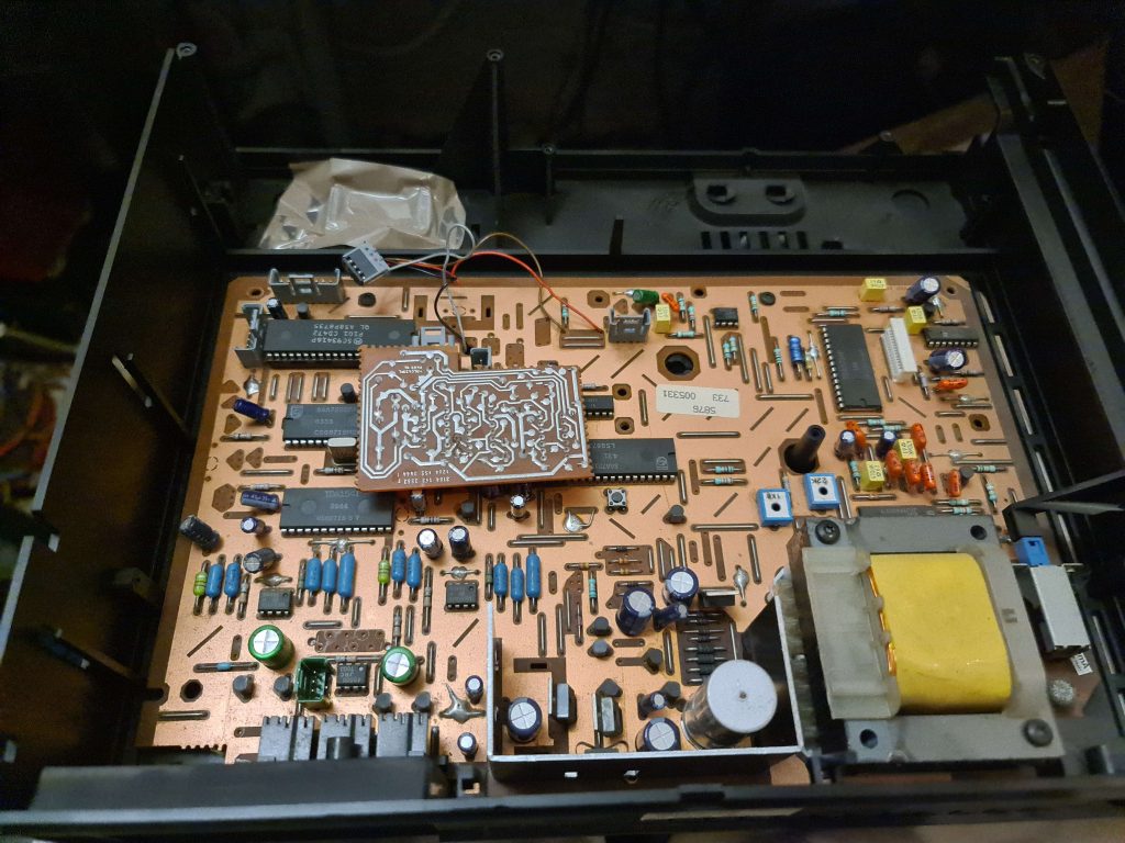

This then provided a nice entry point for an externally provided I²S signal (I²S, funnily enough, having been invented by Philips for the DAC chips for their first CD players), which came from a cheap USB breakout board.


There’s actually a full on USB ΔΣ on there as well, which just so happens to also provide an external I²S. What a world we live in.
This breakout board only accepted sample rates of up to 44100hz however, meaning the oversampling of the now removed chip could not be replicated.
All that was left was removing the muting transistor, as the CD player logic controller, not receiving a “ready to play” from the CD mechanism, had cleverly muted the audio outputs to prevent stray bits from triggering uncomfortable noise while the CD was still seeking (or not playing at all).
All this being done, I now had a purportedly decent USB DAC built from a CD player, but the problem now was that I also wanted to play CD’s, preferably at the same purported quality as the DAC I had just built.
My friend came to the rescue once again, providing me with a junked CD371 player (which, due to it’s VFD display, came in a wider case), which, after transplanting the existing CD player mother board into it, had some convenient space left over for further components.
In this space was installed an Allied Control CHU-12D relay, which I believe was originally intended to switch power inside of military aircraft (26.5VDC being an old aircraft standard for archaic battery reasons, it’s built very ruggedly, and Allied is in the name), which my friend had just laying around31Somehow, and which was chosen purely because it had four contacts as opposed to the more common two.


Using these contacts, the entire I²S signal is simply switched between the output of the CD Decoder IC and the USB provider, which “Just Works”32unlike video games made by a certain developer….
This being a beefy relay designed to withstand a soviet attack, it does need a beefy power supply to trip it.
This was provided by an defunct laptop charger33Also provided by my friend, I owe so much to him, powered from it’s own external 230V input, and the output of which is switched using a large switch which I mounted trough one of the unused output punch-outs in the back of the case.
My friend, for good measure, also installed some industrial surplus film capacitors which he assured me would improve the sound in some way, although I sadly don’t remember what exactly these are supposed to achieve.

Now, using the relay switch on the back, I could (with a delightfully loud Clonk) switch between the CD and USB data, which due to a complete lack of muting would just instantly continue playing wherever they were.
These modifications did have some downsides however.
The move to the larger CD371 (with it’s different screen technology) meant we tried to adapt the existing motherboard to work with the VFD already in the case (counting on commonality built into the motherboards by Philips to simplify reuse). In the process the entire screen driver broke, leaving no way to indicate current playing track or playing time.
The plastic bar that interfaces the power button on the front with the actual pcb mounted switch near the back was also lost during the conversion, leaving me unable to turn the device off.
The removal of the muting circuit also caused some unfortunate complications when playing CD’s, it being there in the first place for a reason.
The main one was a horrible digital scrunching noise whenever playback started, or when skipping to a new track.
Another one was that when pausing, whatever track34With track here I mean the physical track on the CD with the data on it, defined as a single ring, not just a musical track the CD player was reading from would re-re-re-re-re-re-re-re-re-re-re-re-re-repeat35Much like that until playback was resumed.
And least apparent but possibly the most annoying was a loud and startling pop that would happen at seemingly random intervals when a CD was not playing, leading to discomfort whenever the amplifier was on but the CD was done playing.
All of these frustrations led to the latest addition to this loose assortment of audio equipment:
The CD Transport
Since I knew I was going to build a rack, I was checking our national variant of craigslist for cheap rack mounted CD players that I could use (or modify for use) as a transport.
Now, most of these are built for DJ’s and their ilk, and, apart from having undesirable features such as speed controls, non-tray CD mechanism, and USB-mp3 playback, also seem to look quite ugly.
And most of them didn’t even have digital outputs to begin with.
I did eventually stumble upon a CD player which looked just like a regular one, with rack ears attached, and since it was not all that expensive for what it was36According to my friend at least, and had an digital optical output, I ordered it.
Now, after receiving it, it was plainly obvious that the rack mounting aspect was a home-brew performance, with 2 rather crudely bent and beat up ears screwed straight into the metal sides of what was otherwise a regular CD player.
But, I had already bought it, quite liked the VFD display that came with it, and it’s not like I am any good at modifying these things either, so I went with it.
The main remaining challenge was to convert the optical TOSLINK output to a I²S signal that I could retrofit into my DAC, as well as arranging for some switching mechanism so that I could still use the DAC as an output for my PC (where the bulk of my musical collection resides).
Both of these challenges were met using an off-the-shelf I²S / digital input / digital output smorgasbord, specifically one off of my friends shelf as he had a few laying around he wasn’t using anymore.
It’s basically just a breakout board for a Cirrus Logic WM8804 S/PDIF tranciever, which can re-clock digital inputs, extract I²S signals from a digital input, or turn a I²S signal into a digital output.
Having lived in my friends lab for a while though the board did have parts salvaged from it, specifically the Optical Input which was the exact one I wanted to use.
But I was able to turn this annoyance into an opportunity to build a better solution, using similar principles as used for the CD player modifications.
Namely, as a replacement for the missing TOSLINK input I ordered 2 TOSLINK input diodes, which were then wired to the S/PDIF Converter trough a relay, which my friend said would just work.
I’m glad to report that it does just work.


Yes, that is cardboard, and yes, those are tie wraps.
The important part to me is that I got it built and that it works.
The I²S board is powered by an external 12V wall-wart supply trough the barrel jack, with the 12 volt for the relay derived from the screw terminals already on the board.
The positive side is first passed trough a connector, which connects to a cable going to the patch panel, where I mounted a switch to switch the relay and therefore the input.
Very simple stuff, all things considered.
Some might even call it crude.
The I²S output from the board was then wired in place of the USB to I²S breakout mentioned earlier, as I upgraded my PC last year and made sure to choose a motherboard with a TOSLINK output specifically for things like this.
This also means my very expensive computer is not in any way electrically linked to my somewhat sketchy audio experiments37Mains power inputs not withstanding, meaning any unscheduled explosions at the audio end should not impact my PC.
Next up,
Magnetic Media
This writeup has so far failed to include two significant parts of my Audio System, namely my Reel to Reel tape player and my Cassette based field recorder.
For completeness sake I did want to quickly describe those two systems and what purposes they serve.
My Reel to Reel tape recorder is a Teac X-300R, which I received from a friend38A different one this time around who had bought it when it was new and had not used it in some time.
It has been serviced sometime this century, and seems to run just fine (although that’s only with things I’ve recorded myself, any recordings from other machines seem to be running a little slow)
I received along with it an absolute mother lode of tapes, each of which can hold 90 minutes of High Fidelity recording (or 180 minutes of “speech grade” audio when running at a lower speed)
//Pictures should be added here in the future
The machine itself is not actually mounted inside of the rack, because it would take up a lot of space (and even more with spools attached), is itself incredibly heavy, and because of a lack of a suitable mounting solution.
Instead, it is arranged on a shelf elsewhere in my room, with cables for record and playback running along the walls to the patch panel.
Using the patch panel, any source I have (DAC, CD, Casette, etc) can be patched in to be recorded on to tape, and the output can then be played back on any of my equipment, recorded (digitally or onto cassette), or even both at the same time, all with speed and ease.
This is a large reason as to why the patch panel was made.
The idea behind using this antiquated piece of audio equipment while also in possession of a perfectly functional computer and somewhat working DAC is as follows:
I want to be able to listen to music without using my computer, or any computer for that matter.
Part of that is focus, if I don’t have to have my PC and it’s suite of distractions running it’s a lot easier to get reading or studying done.
The physical aspect of the tapes helps with this, as it takes some effort to mount the spools (making quickly putting on a different album difficult), and their linear nature encourages playing the whole thing back to back instead of skipping around.
Reel to Reel tape also sounds very good audio quality wise (if properly recorded using a good machine onto quality tapes from a source which is itself of good quality, of course), and with its high speed and long play time is a perfectly viable alternative to CD’s for my needs.
On top of this, because of it’s use of a magnetic medium, it is as easy to record music as it is to play it back, and it can be re-recorded an indefinite amount of times without immediate degradation.
This is great for when I want to listen to albums only ever released digitally, without using my computer.
I could burn CD’s instead, but I like the reusable aspect of tape for this purpose.
And finally, it’s really fun to look at.
I am still human, and I like pretty things, and watching the reels go round and round.
Then there’s my Cassette recorder, which is a fabled Sony TC-D5, specifically a TC-D5M.
//Pictures should go here
I’ve wanted one ever since I saw Techmoan feature one almost a decade ago now.
It’s sturdy, it’s portable, it’s got VU meters, it sounds excellent, and it’s about the size of a hardcover book.
I bought this one second hand after waiting a few years for a good deal to show up.
It’s in excellent condition, with the belts recently replaced and barely a scratch on it.
Judging by the sticker on the side, it was at one time used by a reporter of some sort (it’s intended use case), which is a fun thought.
I got the TC-D5 not just because I really like the machine itself, but because I wanted a device that had certain characteristics.
Specifically, I wanted a device for portable, high quality music playback, which does not contain a computer and can play back music I have stored 0n my PC.
This is once again to aid in studying, I wanted a device that I could use in class for listening to music while working, an environment in which smartphones are banned and a Digital Audio Player running android could still be a distracting, given how easy it is to scroll trough a massive library of music looking for a certain track instead of studying.
As a secondary purpose, because of it’s great playback quality, it is also used to play what pre-recorded tapes I do have in my setup at home, as a substitute for a proper cassette deck.
As a neat bonus, it fits exactly into the Pelican Case I have, with room left for a number of cassettes as well.

The main downside with this machine39for my purposes is the very poor battery life; it takes 2 D cells and eats trough them in a few hours.
My plan is to build an external lithium-ion battery pack, which just feeds 6 volts into the external input jack, and to use a “wall adapter” when using it at home.
And another complication is that, being a portable design, it is a bit harder to use with my rack mounted audio system than a rack mounted tape recorder would be.
As it is also much better than any rack mounted cassette player I could afford would be, I have instead installed a sliding shelf onto my rack where it now lives, meaning I can pull it out like a drawer and then use it comfortably from a standing position, with trailing cables going out behind it down into the guts of the rack.
None of this is a deal breaker, as much like with the reel to reel, I simply like using cassettes, they’re fun.
Speaking of which, I also bought a number of cassettes second hand, mainly type II, although there are some type IV’s as well that I had managed to pick up.
//More pictures here
I ended up with more than I had planned for, but at least I won’t have to re-record any quite as often this way.
Recently, I’ve also acquired a second hand PCM-7030 DAT player, for a bargain price.
I would have more to say about it if it didn’t stop working 2 days after purchasing it, such is the risk of second hand equipment.
In theory its a great fit for my system: the lossless and digital audio advantages of a CD, with the record-ability and fun of tape.
This is rather outdone by it’s failure to work though.
I hope to fix it up sometime, but for now it’s on the “to do” pile.
Everything Else
I love blinkenlichten, so 2 Rack Units are devoted to music visualization.
The main one is a Fungeneration RTA-31 Frequency Analyzer, augmented by a t.racks DB meter (both featured on techmoan).
//Pictures here, later
Now these are not used (nor good enough) to really measure anything, I just like to try and see if I can pick out instruments from their frequencies on the RTA-31, and still enjoy the lightshow when just listening.
In the future I hope to also have a spectrogram display, but I would likely have to build that myself, and have yet to find a suitable screen to do that with.
I’ve also recently bought a second hand (and way too large) Allen & Heath ZED12FX mixer panel.
//More pictures here
It can rack mount, but it both takes up way more space than my current cabinet affords, and is ill positioned to be used while seated at my desk (which is from where it would be operated following my original use case)
A yet to be announced future project is intended to solve both problems.
The Whole
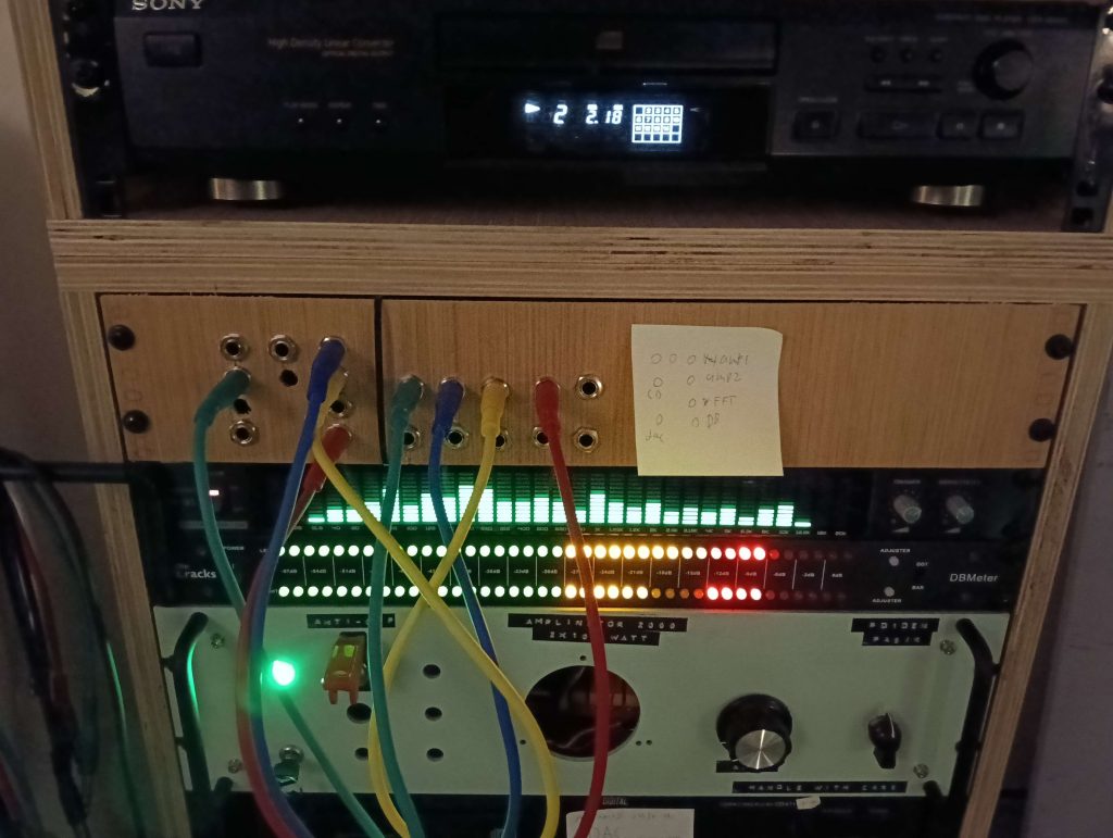
Here is how all of this looks integrated into my fabulous 49cm rack

From top to bottom:
- 3 Blanking Plates
- 1U power supply (custom)
- 4U radio transmitter (panel only)
- 1U Satellite Connection Switchover housing (for parts)
- 1U housing
- 2U Sony CD player (used as transport)
- 2U Shelf with Sony TC-D5m Cassette Recorder
- 3U PCM-7030 DAT Recorder
- 2U Patch Panel (custom)
- 1U DB meter
- 1U RTA-31 Spectrum Analyzer
- 3U Amplinator 10,000
- 2U Philips CD Player (used as DAC)
- 1U Power Distribution Unit
- 1U Ventilation Grille
- 1U Power Distribution Unit
- 2U Power Distribution Unit
- 1U shelf with 2 servers
- 1U gigabit network switch (20 ports)
- 2x 1U Redundant Server Power Supplies (broken)
Future Plans
I plan to build a relay attenuator, and am looking at this design to do so.
The reason is that I want a way to remotely control the volume, without using a motorized potentiometer or Integrated Circuit solution.
I don’t want to use an Integrated Circuit because I want it to be as transparent as possible40Just because I put so many things in my audio path does not mean I don’t want the option of theoretical transparency, and relays are a very straightforward way to do so, and I don’t want a motorized potentiometer because I want direct volume control (as in, being able to set a precise and specific volume directly and instantly, as opposed to being limited to “up” and “down”).
This also allows me to use a micro controller to set an arbitrary volume curve (meaning I can switch between logarithmic, linear, or experiment with more obscure audio tapers), which would then be controlled by a potentiometer (or potentiometers) mounted elsewhere and sending data back to the micro controller.
This is to be integrated with my patch panel, so that the volume control can be arbitrarily inserted where it’s wanted (between the DAC and the Amplifier, or between the Reel to Reel and the Headphone Amplifier, etc etc)
I also plan to build a new DAC to replace the tortured CD 104 I’m using now, based on PCB’s designed by my oft mentioned friend.
I already have a case for it (from the same friend, I owe him so much), which is to hold the DAC, the power supplies, as well as the TOSLINK switching and decoding circuitry, and will fit ever so neatly into the rack.
//Pictures should go here
I am also looking at getting a decent record player at some point in the future, mainly to be able to play older and obscure recordings, not because of it’s purported “hi-fi” qualities.
I also feel that there is room in this set up for a small (4 channel) mixer, to be wired in as needed trough the patch panel, and placed somewhere on my computer desk.
It is more likely to impact the audio signals than a plain relay based switching solution by it’s very nature, being an active component, but it would allow me to, for example, listen to a CD or tape recording while at the same time working at my computer, without being unable to hear sounds produced by my computer.
In the end, the more options the better.
I want to not just sit in front of this system, I wish to be inside it, to be in total and complete control of it’s topography and it’s use, seamlessly navigating between half a dozen sources and as many destinations, with as little friction and digital chicanery as possible.
That is, in the end, the purpose of the entire Great Controller project, to be in control, to make a man machine interface that fits this particular man like a proverbial glove.
To make the system not merely useful, but a joy to use.